ISSN ONLINE(2278-8875) PRINT (2320-3765)
ISSN ONLINE(2278-8875) PRINT (2320-3765)
| Riya Philip PG Student [PEPS], Department of EEE, Amal Jyothi College of Engineering, Kanjirapally, Kerala, India |
| Related article at Pubmed, Scholar Google |
Visit for more related articles at International Journal of Advanced Research in Electrical, Electronics and Instrumentation Engineering
Power Quality means maintaining purely sinusoidal current wave form in phase with a purely sinusoidal voltage wave form throughout in a power system. Due to intensive use of power converters and other non linear loads in industries, an increasing deterioration of the power system voltage and current waveforms has been observed. The most important cause for degrading power quality are harmonic distortion and low power factor. Conventionally, Passive filters have been used as a solution to solve harmonic current problems, but they are not capable of mitigating the low power factor problems. So an improved method of Active Power Filter (APF) used to eliminate the disturbances in current. This paper examines the control of Shunt Active Power Filter (SAPF) with Synchronous Reference Frame (SRF) detection method. Here a twelve pulse diode bridge rectifier will be the non linear load and the switching frequency is set to 10 kHz. Simulation analyses are done using Matlab/Simulink software.
Keywords |
| Shunt Active Power Filter, Synchronous Reference Frame method, Hysteresis Band Current Controller |
INTRODUCTION |
| We know that nonlinear loads in power system create so many unwanted effects in power system. These nonlinear loads are constructed by nonlinear devices, in which the current is not proportional to the applied voltage. The currents produced by these loads result in distorted voltages and currents that can adversely impact the system performance in different ways. These harmonic currents are injected into the supply systems and pollute the power line causing power quality problems to many power quality critical loads. The injected current harmonics cause line voltage distortion and notches which is a major problem for utilities. The distorted voltage frequently results in malfunction or tripping of other linear/nonlinear loads. All these can adversely affect the power factor of the system. In fact, a low power factor reduces the power available from the utility grid. The loads having low PF will draw more current than the loads having high PF for the same amount of power. |
| Both harmonic distortions and low power factor adversely effects the smooth functioning of power system. They reduce the quality of voltage and current waveforms. If, presence of harmonics distorts the pure sinusoidal system waveform then, low power factor will cause the voltage or current waveform to lag or lead the other. So inorder for the quality of supply voltage and improved efficiency, mitigation of harmonics and power factor improvement is necessary. Active power filters are devices used for harmonic mitigation, but if a better control method is used it will also help to improve power factor of the system. This paper examines the control of Shunt Active Power Filter (SAPF) with Synchronous Reference Frame (SRF) detection and Hysteresis control. |
II. LITERATURE REVIEW |
| Power system harmonics are integer multiples of the fundamental power system frequency. The main sources of waveform distortion are electric arc furnaces, fluorescent lamps, electrical machines, transformers etc. The commonly used power electronic devices such as rectifiers, inverters, cycloconverters etc. contribute large amounts of harmonics. |
| Harmonics can cause a variety of unwelcome effects like signal interference, over voltages, data loss, equipment heating, malfunction, very high neutral currents, random tripping of circuit breakers, premature failure of transformers and uninterruptible power supplies and damage. Rotor heating and pulsating output torque caused by harmonics can result in excessive motor heating and inefficiency. High levels of power system harmonics can create voltage distortion and power quality problems [1]. These harmonic distortions in power distribution systems can be suppressed using mainly two approaches. One is Passive Filtering and the other is Active Power Filtering. |
A. Passive Filter |
| The passive filtering is the simplest conventional solution to mitigate the harmonic distortion. Passive filters are inductance, capacitance, and resistance elements configured and tuned to control harmonics. But, they do not always respond correctly to the dynamics of the power systems. They have many disadvantages such as fixed compensation, large size and resonance problems. Passive filters are known to cause resonance, thus affecting the stability of the power distribution systems. Frequency variation of the power distribution system and tolerances in component values affect the passive filtering characteristics. So passive filters might not be able to meet the harmonic limitations of international standards. This may required a retrofit of new filters [2]. |
B. Active Power Filter |
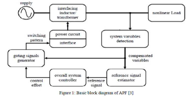
| Remarkable progress in power electronics had raised the interest in Active Power Filters for harmonic mitigation. APFs performances are independent of the power distribution system properties. Figure 1 shows the basic block diagram of active power filter. The working of active power filter consists of mainly three stages. They are: Signal conditioning, Derivation of compensating signal and Generation of gating signal. |
 |
| Signal conditioning refers to the detection or sensing of harmonics in the power distribution line. As shown in Figure 1, the reference signal estimation is initiated through the detection of essential voltage/current signals sensed by using potential transformers, current transformers etc. The next stage is the derivation of compensating signal from the disrupted wave consists of both fundamental wave and the harmonic content. It can be done by different methods like Fourier transformation method, Instantaneous Reactive Power Theorem, Synchronous Reference Frame Theorem, Synchronous Detection Theorem etc. The third stage is the generation of gating signal for harmonic suppression. So many control techniques like space Vector PWM, repetitive control, hysteresis current control, dead beat control, sliding mode control, fuzzy control etc have been introduced and applied to various configurations of active power filters [3][4]. |
III. APPLICATION OF SRF METHOD FOR HARMONIC MITIGATION |
| Synchronous dq frame is derived from the space vector transformation of the input signals, which initially are achieved in the abc coordinates from the sensors and then transformed into the dq coordinates by means of the Park transformation. Here abc coordinates are considered as stationary reference frame and dq coordinates are considered as rotating reference frame with fundamental angular frequency. In dq frame the fundamental currents are appeared as dc component and the harmonics as ac component. The dq frame components are calculated using the Park transformation. |
| The active and reactive components of the three phase system are represented by the direct and quadrature components respectively. The fundamental component (dc component) is eliminated by using a high pass filter. Then the harmonic signals (ac component) are converted back to abc coordinates using inverse transformation. These signals are further used to generate controlling pulses inorder to trigger the switches of inverter to inject inversed harmonic waves in to the power system. |
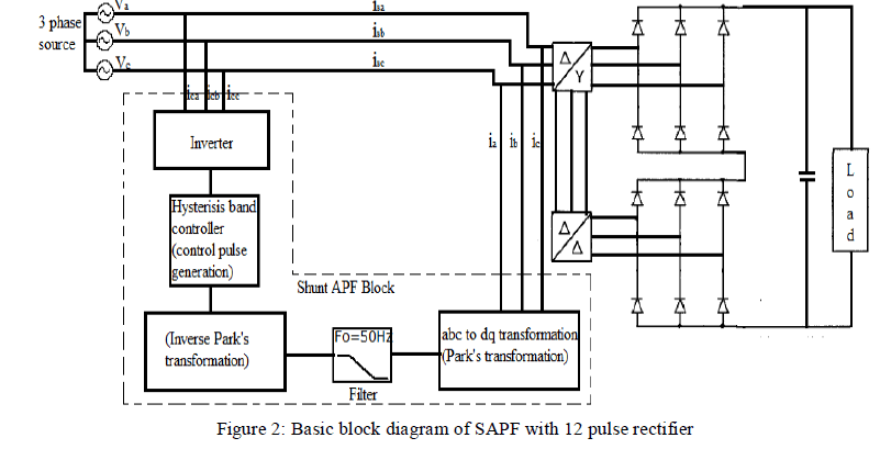
| Figure 2 shows the compensation principle of a three phase shunt active power filter with a 12 pulse rectifier as nonlinear load. The source is a balanced Y-connected three phase voltage source where the phase voltages are Va , Vb and Vc, while the nonlinear loads connected to each phase produces nonlinear load currents ia, ib and ic . The supply is given to the two 6 pulse rectifiers through a transformer whose primary is delta connected and secondary have two windings-star and delta, so as to provide 30° phase shift to each supply [5]. |
 |
| When the SAPF block is not operating the nonlinear load current are themselves the line currents isa, isb and isc, which causes degradation in power factor and introduces harmonic distortion. When the SAPF block is operating, it injects currents ica, icb and icc equal in magnitude but in phase opposition to harmonic current in each of the lines. This compensates the harmonic distortion and makes the source current balanced and sinusoidal while the load current remains nonlinear. The Shunt APF block is basically divided into three parts. The first part consists of reference signal generation by using Park's transformation. The second part is a control block which does necessary computations and operations to generate the control pulses. In order to get precise instantaneous current control, the current control method must supply quick current controllability, thus quick response. For this reason, hysteresis band current controller is here used for active power filter. The line currents can be implemented to generate the switching patterns for the inverter. There are various current control methods proposed for such active power filter configurations, but in terms of quick current controllability and easy implementation hysteresis band current control method has the highest rate among other current control methods such as sinusoidal PWM. This reference is fed to the IGBT based Voltage Source Inverter (VSI). A dc capacitor usually works as the source of power for the VSI. According to the switching pulses the inverter provides current waveforms that are opposite in phase to the harmonic waves. They are injected to the system using coupling inductors or transformers which in turn cancel out the effect of harmonic waves from the source current [6][7]. |
IV.SIMULATION ANALYSIS |
| Software simulation of Active Power Filter circuit with three phase diode bridge rectifier is done in MATLAB/Simulink. In the sample circuit of the considered system, a three phase twelve pulse diode bridge rectifier having two six pulse diode bridges is taken as the non linear load. The input supply is 415V and the switching frequency is set to 10 kHz. |
A. Simulink Model of Twelve Pulse Diode Bridge Rectifier |
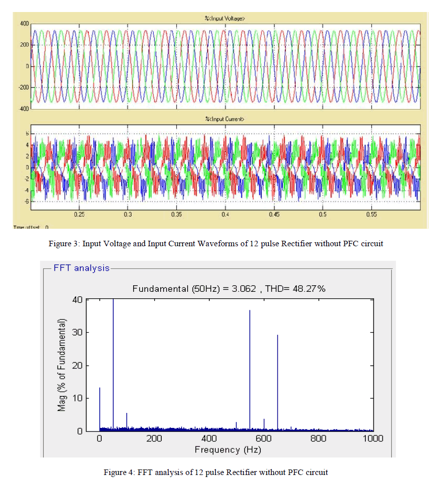
| The three phase 12 pulse diode bridge rectifier is simulated without any PFC circuits in MATLAB. The converter input source voltage and current waveforms are as shown in Figure 3. Here we can see that the source current is distorted and also it is not in phase with the source voltage. The Total Harmonic Distortion (THD) is measured as 48.27% and the input power factor of the converter is displayed as 0.87. The FFT analysis for harmonic content in source current waveform is as shown in Figure 4. |
 |
B. Simulink Model of 12 Pulse Rectifier with APF |
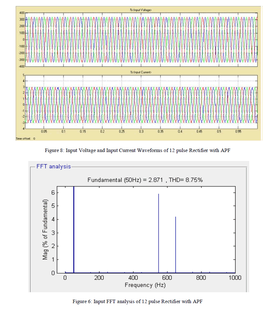
| The three phase twelve pulse diode bridge rectifier is simulated with shunt active power filter. The THD of the circuit is measured as 8.75%. The mean power factor displayed here is 0.953. The input current and voltage waveforms of the 12 pulse rectifier with APF are as shown in Figure 5. The FFT analysis for harmonic content in source current waveform is as shown in Figure 6. |
 |
V. CONCLUSION |
| Shunt APF offers better performance by improving power quality by significantly reducing the harmonic components in currents and correcting the power factor. The result of simulations performed in this work shows that synchronous reference frame detection method provides better power quality improvement. Computer aided simulations are carried out using MATLAB/Simulink simulation package, where the load is three phase twelve pulse diode bridge rectifier with R load. The harmonic filtering performance of the shunt APF is validated by a detailed THD analysis. Without APF circuit, the THD measured was 48.27% and the power factor obtained was 0.87. Then with APF circuit the THD is reduced to 8.75% and power factor is improved to 0.953. The analysed results conclude that the shunt APF topology effectively filters harmonic currents of low and high frequencies to obtain sinusoidal source current. Shunt active filters allow the compensation of current harmonics and unbalance, together with power factor correction, and can be a much better solution than the conventional approach (capacitors for power factor correction and passive filters to compensate for current harmonics). |
References |
|