International Journal of Advanced Research in Electrical, Electronics and Instrumentation Engineering
ISSN ONLINE(2278-8875) PRINT (2320-3765)
ISSN ONLINE(2278-8875) PRINT (2320-3765)
Mrs.Bhagyalakshmi N1, Dr.Rekha K R2 , Dr.Nataraj K R3
|
| Related article at Pubmed, Scholar Google |
Visit for more related articles at International Journal of Advanced Research in Electrical, Electronics and Instrumentation Engineering
In this paper, Design of FIR Filter using System Level Tools like Simulink in Xilinx System Generator and hardware based FIR Filter Design using Verilog has been proposed. System level tools like Xilinx System Generator are used to design an efficient DSP Algorithms and Applications on FPGA. Both the designs have been further synthesized on Xilinx Spartan3 FPGA kit. Finally, a comparison is done between the results obtained from the software simulations and those from FPGA
Keywords |
| DSP, FIR filter, FPGA, Simulink, System Generator. |
INTRODUCTION |
| Digital Signal Processing Techniques are used in many applications, mainly in communication field, video processing and multimedia.DSP algorithms requires a number of mathematical operations to be performed very quickly.DSP functions mainly contain Digital Filters and Transforms that have advantages over analog designs. Digital filters have become an increasingly attractive replacement for analog filters due to recent advances in semiconductor technology. As the speed of operation increases, either to permit real-time processing of wide-band signals or to time share the arithmetic unit, there is a rapid increase in hardware complexity, as measured by the number of IC’s used, and in power consumption. The major factor causing this increase lies with the high-speed multipliers [1]. |
II. RELATED WORK |
| MATLAB based Simulink Tool helps to design the model based diagram and simulation, automated code generation and verification of corresponding design on high end FPGA’s. Filter Design and Analysis (FDA) Tool is a powerful tool in MATLAB Signal Processing Tool box, with the help of which we can design and analyze different types of Filters [2]. |
| The recent progress in software tool development is to support DSP applications widely in FPGAs. System Generator for DSP™ is the Industry’s leading high-level tool for designing high-performance DSP systems using FPGAs [3].System Generator tool provides Simulink libraries to design Arithmetic, Logical, Mathematical, Memory blocks and DSP functions [4]. The DSP functions include FIR Filters and Transforms. In this paper we are designing the FIR Filters using System Generator models with the help of FDA Tools. |
| The designing of a Filter essentially comprises of two basic steps that completes the design process. The first step is the generation of coefficients and the second step constitutes the simulation of filter using the generated coefficients. Although FIR Filter design is complicate, the advantages persisting allows them to be widely used for filtering applications when compared to IIR Filters. IIR filters do not provide stability at higher orders whereas the FIR counterparts are always stable and are particularly useful for applications which require exact linear phase response [8]. The paper is organized as follows: Section 2 gives a Brief review of the FIR Filter design. Section 3 presents the FIR Filter Design using System Generator. Section 4 presents the results and comparison of the FIR Filter design. A conclusion is given in Section 5. |
III. FIR FILTER DESIGN |
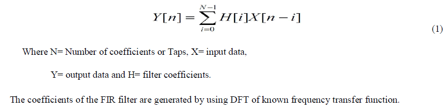
| In digital design, the Finite Impulse Response (FIR) can be viewed as a functional diagram shown in the Fig 1 and implemented using the equation (1) given below [5]. |
 |
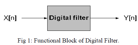 |
| Here we have designed parallel implementation of 4-Tap FIR Filter as shown in the Fig 2.The filter contains mainly multiplication block, adder block, and flip-flops. The flip-flops act as registers to store the data temporarily. The input data is multiplied with filter coefficient. Results are stored in register. Next multiplied data is added with the data in the register to faster the process. Hence delay will be avoided. Due to the usage of registers glitching problem will be filtered. So it reduces the power consumption of the design. |
| The design is in its transposed form. This design is basic FIR Filter multiplier based design. Now a day’s many multiplier less architectures are available in market. |
 |
IV. FIR FILTER DESIGN USING SYSTEM GENERTOR |
| System generator is a high level system design tool for creating custom DSP blocks on FPGA easily. System generator basically provides two key tools: |
| ïÃâ÷ Blocks for building the model. |
| ïÃâ÷ Hardware generator model. |
| Simulink provides a test environment for the design [9]. |
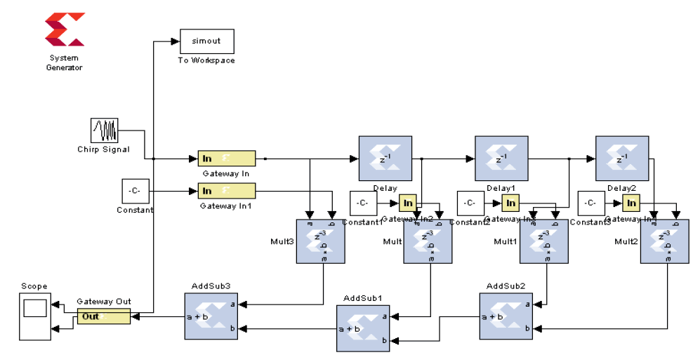
| Fig 3 shows the 3-Tap Filter design. The input is a Chirp signal which gives the up frequency or down frequency with time and Output signal is a linear Chirp signal (sine wave whose frequency varies linearly with time). |
| The design is a Low Power 3-Tap FIR Filter design using Least Square method as shown in the Fig 3. Least mean square (LMS) algorithm is used in adaptive filters to find the filter Coefficients that relate to producing the least mean squares of the error signal (difference between the desired and the actual signal). |
| It is one of the optimal filter design methods for designing an FIR Filter. The basic idea is to generate the filter coefficients again and again until a particular error is minimized. The purpose of most of the filters is to separate the desired signal from undesired signal or noise. As the energy of the signal is related to square of the signal, a squared error approximation criterion is appropriate to optimize the design if FIR filters. The choice of LMS algorithm lies in its simplicity of implementation, Stable and robust performance against different signal conditions. |
| The input signal frequency is 100MHZ and the Frequency specifications of Filter are as follows: |
| Fs=48000 Hz, Fpass=9600Hz, Fstop=12000Hz. |
| The coeffiecients are generated by using FDA tool. We have to export the coeffiecient values to MATLAB workspace and save as a variable name Num. Num contains 4 coeffiecients as given below. |
| coeffiecient1= 0.180209484969501 |
| coeffiecient2= 0.407209809882283 |
| coeffiecient3= 0.407209809882283 |
| coeffiecient4= 0.180209484969501 |
 |
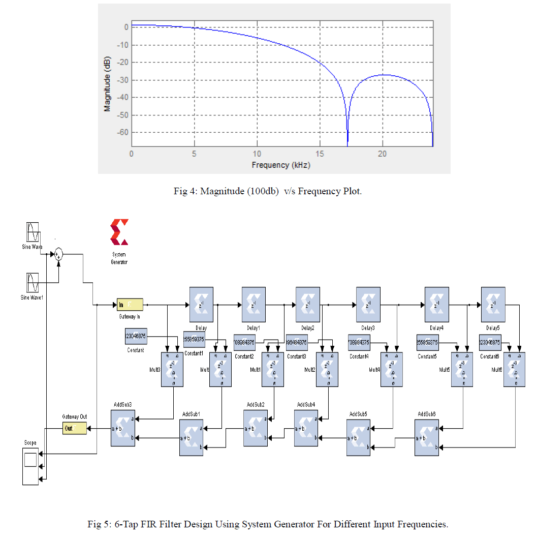
| The magnitude (100db) and frequency plot is as shown in Fig 4. |
 |
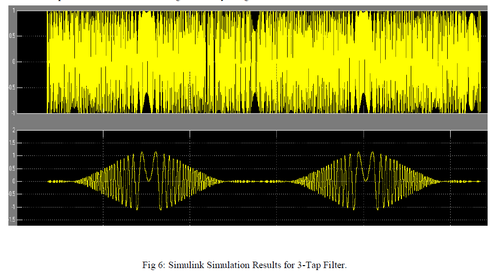
| The Fig 5 shows the 6-Tap Filter design using 2 different input frequencies. The input signal is a sine wave with 2 different frequencies.The coeffiecients are generated by using FDA tool. It contains 7 coeffiecients. |
 |
 |
V.RESULTS AND COMPARISON |
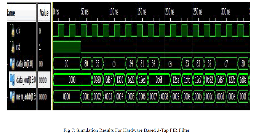
| The Simulink Simulation results for 3-Tap Filter using System Generator is shown in the Fig 6. It contains Chirp signal as an input (above) and filtered output (below) in Fig 6. |
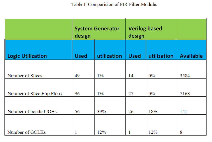
| The Verilog based 3-Tap FIR Filter Simulation results are as shown in the Fig 7.The input for hardware based 3-tap FIR filter is a Chirp signal which is generated with the help of simout as shown in Fig 3 in text form to FIR design .Then simulated using I-sim simulator. |
| Comparision for System Generator based and Hardware based FIR Filter module is as given below. |
 |
VI.CONCLUSION |
| This paper describes a System Level approach towards the implementation of FIR Filters using System Generator and subsequent Verilog synthesis on Field Programmable Gate Arrays (FPGA). The parallel implementation of FIR Filter is excellent in terms of area and System Generator model greatly increases the speed of operation in the implementation of the FIR Filter. With the help of System Level tools we can design any DSP model in short time and is suitable for high speed FPGA’s. |
References |
|