International Journal of Advanced Research in Electrical, Electronics and Instrumentation Engineering
ISSN ONLINE(2278-8875) PRINT (2320-3765)
ISSN ONLINE(2278-8875) PRINT (2320-3765)
Deepan Raj.B1, T.V.P.Sundararajan2, K.Shoukath Ali3
|
| Related article at Pubmed, Scholar Google |
Visit for more related articles at International Journal of Advanced Research in Electrical, Electronics and Instrumentation Engineering
To improve the performance of system in terms of processing power, a new architecture and clocking technique is to be realized in this paper. To process the signal in Embedded Parallel Systolic Filters (EPSF) and to eliminate the noise present in the signal using flag-bit and flicker clock condition. Kalman filter and extended kalman filter are the filtering techniques used by systolic arrays that can simultaneously triggered on all data elements with different clock cycles. Kalman filter and extended kalman filter to work in two conditions namely with and without flag-bit, flicker clock are to be synthesized and compared.
Keywords |
| EPSF, Flag-Bit, Flicker Clock, Kalman Filter and Extended Kalman filter. |
INTRODUCTION |
A. Systolic Array |
| Systolic algorithms are concurrent versions of sequential algorithms suitable to run on array processors that execute operations in the so-called systolic manner. Systolic arrays are generally classified as high-performance, specialpurpose VLSI computer systems suitable for specific application requirements that must balance intensive computations with demanding I/O bandwidths. Systolic arrays are tremendously concurrent architectures, organized as networks of identical and relatively simple processing elements that synchronously execute operations. Modular processors interconnected with homogeneous (regular) and local interconnections provide the basic building blocks for a variety of algorithms. Systolic algorithms address the performance requirements of special-purpose systems by achieving significant speedup through parallel processing and the prevention of I/O and memory bandwidth bottlenecks. Data are pumped rhythmically from the memory through the systolic array before the result is returned to the memory. The global clock and explicit timing delays synchronize the system. |
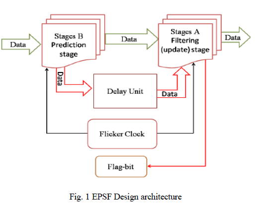 |
| A new technique of embedded parallel systolic filters (EPSF) is proposed in this paper and is depicted in fig.1. The EPSF combines the multiple Parallel Element (PE) layers of the original systolic array into a single PE layer with a set of feedback registers in a pipeline structure. Data are originally passed to stage B for pre-processing, and the flag-bit is then observed to decide whether to enter stages A or the delay unit until the flag-bit changesits status. An additional unit of control signal digital circuit is required to produce the control signals for data input selection, cell memory clearance and operation mode control. |
FILTERS |
A. Kalman Filter |
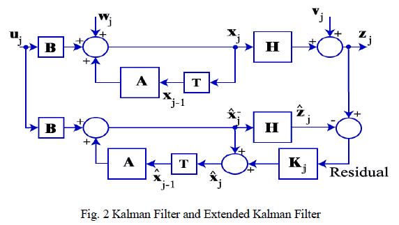
| Kalman Filter is based on minimizing the mean square error recursively. Therefore, it can work well in estimating the unknown states of a noisy dynamic process. The Kalman filter, also known as linear quadratic estimation (LQE), is an algorithm that uses a series of measurements observed over time, containing noise (random variations) and other inaccuracies, and produces estimates of unknown variables that tend to be more precise than those based on a single measurement alone. More formally, the Kalman filter operates recursively on streams of noisy input data to produce a statistically optimal estimate of the underlying system state. The filter is named for Rudolf (Rudy) E. Kálmán, one of the primary developers of its theory. |
| The block diagram of kalman filter is shown in fig.2. The algorithm works in a two-step process. In the prediction step, the Kalman filter produces estimates of the current state variables, along with their uncertainties. Once the outcome of the next measurement (necessarily corrupted with some amount of error, including random noise) is observed, these estimates are updated using a weighted average, with more weight being given to estimates with higher certainty. Because of the algorithm's recursive nature, it can run in real time using only the present input measurements and the previously calculated state no additional past information is required. |
 |
B. Extended kalman Filter |
| Extended Kalman filter (EKF), it is the nonlinear version of the Kalman filter. A Kalman filter that linearizes the current mean and covariance is referred to as an extended Kalman filter or EKF. The state transition and observation models need not be linear functions of the state but may instead be (differentiable) functions. |
| The extended Kalman filter arises by linearizing the signal model about the current state estimate and using the linear Kalman filter to predict the next estimate. This attempts to produce a locally optimal filter, however, it is not necessarily stable because the solutions of the underlying Riccati equation are not guaranteed to be positive definite. The familiar structure of the extended Kalman filter is retained but stability is achieved by selecting a positive definite solution to a faux algebraic Riccati equation for the gain design. |
FLAG-BIT |
| The conception of systolic or chained processing can be described as the implementation technique that partitions the execution of a given operation into the number of subsequent steps as far as possible from the same duration.Furthermore, each section assigned to a particular step can exploit standalone technical resources. Executions of single packet data requires less clock cycles, and overhead can be effectively hidden by a parallel operation. Synchronous systolic is composed of stages, each of which is dedicated to a different stage of processing. Individual stages are separated by embedding additional registers. As addressed in our design using appropriate circuitry structures, systolic or chained processing might impose different types of conflicts (data and control). |
| To solve this problem, a flag bit is assigned for each stage indicating its status. A flag bit of 0 means the stage has finished the process and is ready to accept other data; otherwise, data coming from the previous stage will enter in a delay unit of 100 ns each cycle and will make the previous stages work on another smaller clock cycle at 50 ns until the flag bit becomes 0. |
FLICKER CLOCK |
| Flicker clock management can have a strong impact on the reduction of processing delay in FPGAs. In most modems, FPGAs have dedicated clock managers for solving high speed clock distribution problems in high-density designs. This design uses an indicator for systolic stages of the filters called flag-bit, which works when a delay occurs in any filter stage. Flag-bit gives design high control on data transmission and early alerts to prevent data conflict. This new technique is very efficient and reliable for parallel processing systems and gives the best results to satisfy parallelism. |
| Several clock managers have been introduced to FPGA chips. They can perform clock buffering, drive the distribution networks, and simultaneously eliminate clock skew. They can also produce phase shifts and duty cycle adjustment. In addition, clock managers can be used to synchronize several components in a system. Although they perform their intended function well, current FPGA clock managers are incapable of performing dynamic clock management because their dividers cannot perform dynamic division or multiplication. If a flicker clock is added to the existing FPGA clock managers, they can be used for clock management. As a result, clean frequency changes can take effect within a clock cycle. |
| Division of the input clock is performed by creating a loop of T-flip-flops driven by the input clock. To create the necessary clock, more than one clock signal must enter into the multiplexer that feeds the systolic stages through necessary clock signals dependent on the status of the flag-bit. |
RESULTS AND DICUSSSION |
A. Kalman Filter |
| In this section kalman filter is simulated with flicker clock circuit in model sim software and the results are compared with the presence of flag-bit and without flag-bit.This stage is mainly used for calculating prediction values. |
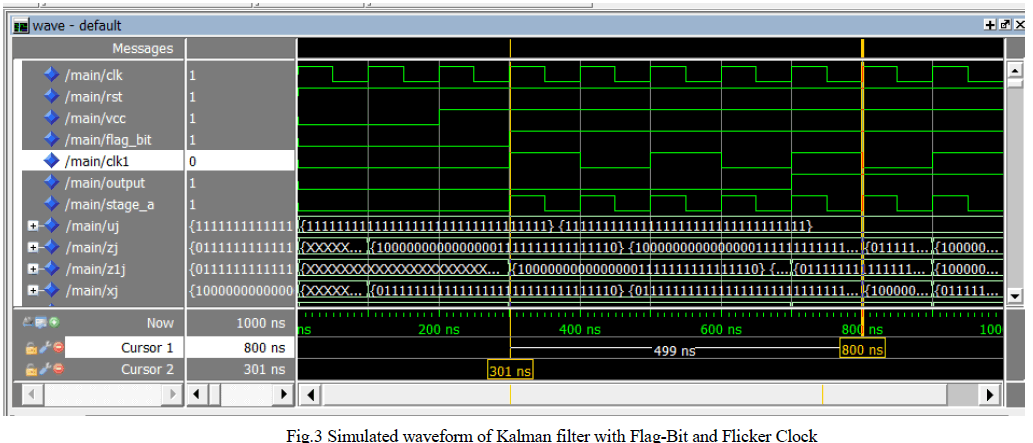 |
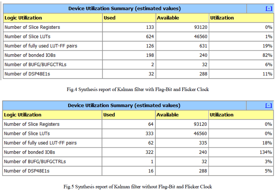
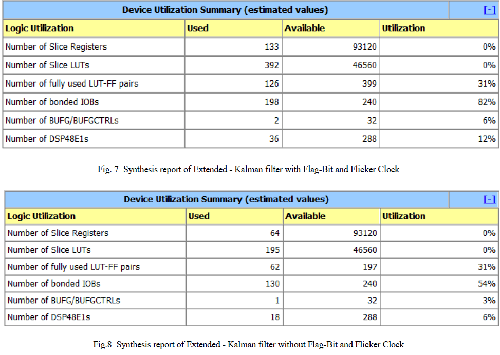
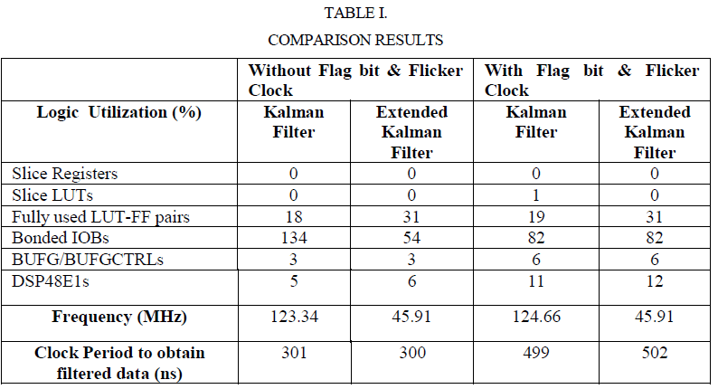
| In the fig.3 waveform the input for normal clock (clk) is also feeded to flicker clock (Clk1) . At the initial condition the vcc and flag-bit is set to 0, this is done in order to allow flicker clock to start its operation. After some iteration the vcc is set to 1, then flicker clock will start its operation . After this flag-bit is also set to 1. The input data (signal) is entered in uj. The pulse till the vcc and flag-bit lies in 0 value is called without flag-bit condition. Once the vcc and flag-bit are set to 1 then the operation starts. The data sent in uj normally has noise . It is filtered and obtained in zj and xj. Here zj and xj are the prediction values . The time period taken to obtain the filtered data is calculated from the difference between the flag-bit 1 condition till the bit change is obtained in zj and xj. Kalman filter is synthesized in Xilinx 14.2 software using Virtex 6 FPGA family for both the conditions and the design summary for the two conditions is shown in fig. 4 and fig. 5. |
 |
B. Extended Kalman Filter |
| In this section extende kalman filter is simulated with flicker clock circuit in model sim software and the results are compared with the presence of flag-bit and without flag-bit. This stage is mainly used for updating the values. |
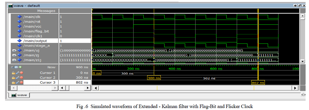 |
| In the fig.6 waveform the input for normal clock (clk) is also feeded to flicker clock (Clk1) . At the initial condition the vcc and flag-bit is set to 0, this is done in order to allow flicker clock to start its operation. After some iteration vcc is set to 1, then flicker clock will start its operation . After this flag-bit is also set to 1. The input data (signal) is entered in uj. The pulse till the vcc and flag-bit lies in 0 value is called without flag-bit condition. Once the vcc and flag-bit are set to 1 then the operation starts. The data sent in uj normally has noise . It is filtered and obtained in zj and z1j. Here z1j is the update stage. The time period taken to obtain the filtered data is calculated from the difference between the flag-bit 1 condition till the bit change is obtained in zj and xj. Here zj is called updated values. Extended Kalman filter is synthesized in Xilinx 14.2 software using Virtex 6 FPGA family for both the conditions and the design summary for the two conditions is shown in fig. 7 and fig. 8. |
 |
 |
CONCLUSION |
| An embedded parallel systolic filters is designed using kalman filter and extended kalman filter. Both the filters are simulated using modelsim-6.3f version and the results are obtained for two conditions namely with and without flag-bit and flicker clock . The noise free output is successfully obtained with EPSF architecture in both kalman filter and extended kalman filter. The synthesis results are also obtained from Xilinx 14.2 software using designed using virtex 6 FPGA family. |
ACKNOWLEDGEMENT |
| The authors thank the Management and Principal of Bannari Amman Institute of Technology, Sathyamangalam for providing excellent computing facilities and encouragement. |
References |
|