International Journal of Advanced Research in Electrical, Electronics and Instrumentation Engineering
ISSN ONLINE(2278-8875) PRINT (2320-3765)
ISSN ONLINE(2278-8875) PRINT (2320-3765)
Umar Farooq Siddiqui1, Pallavi Bondriya2
|
| Related article at Pubmed, Scholar Google |
Visit for more related articles at International Journal of Advanced Research in Electrical, Electronics and Instrumentation Engineering
In this paper soft starting of asynchronous motor via two different power electronics devices is obtained as well as this paper give comparative performance of asynchronous motor for same firing angle applying on two different power electronics devices first one is thyristor and second one is insulated gate bipolar transistor. This paper employ the topology in order to minimizing the adverse effects of high inrush currents in induction motors starting torque transients with the help of electronically controlled soft-starting voltages utilizing silicon-controlled rectifiers (SCRs). In this paper fundamental frequency and THD is calculated in both for R-L load and asynchronous motor by various firing angles, and influence of load variations in terms of firing angle has been investigated for Thyristor and IGBT (Insulated Gate Bipolar Transistor).
Keywords |
| Variable speed induction motor, Soft Starter, Thyristor, IGBT, Fundamental Frequency, THD. |
INTRODUCTION |
| Harmonics are cause of voltage changing and increasing fluctuating torque, surge as well as creating losses in supply line which occur great problems in the starting of large asynchronous motor. Harmonic is component of a sine wave that is an integer multiple of the fundamental wave. In case of increase harmonics cause losses and depreciation in the transmission and distribution equipment and power consumers, so to control harmonic it is necessary to use some technique to reduce harmonics and increasing quality of power as well as make it healthier for devices. Because of harmonics supply voltage fluctuates, resulting in the failure of motor starting. In this paper we have discussed about solution of all above types of problems and remove this by using soft starter technique. There are a lot of methods adapting to controlled harmonics in these one method is to insert filter between the supply and asynchronous motor. If the supply output voltage contains high frequency harmonics, these can be reducing by low-size filter. |
| Soft Starting gives jerk free and smooth start to the induction motor. Subsequent to this, high frequency component from this voltage can easily be attenuated by using a semiconductor based control circuit model. This controlled circuit not only reduces harmonics as well as reduce problem of direct online starting and give smooth and jerk free stating to the machine. AC voltage controllers or voltage regulator or control circuit unit can use highly speed power electronics switches such as thyristors, Insulated gate bipolar transistor, Bipolar Junction Transistor etc. Now present day’s thyristor and IGBT more commonly employed in soft starting of induction motor. |
| These techniques are more economical, convenient and reliable. Voltage and harmonics as well as THD can be controlled by controlling firing angle of thyristors. This paper analyze the feasibility of controlled convertors and modified new methods to analyze an obtain the input current instability components and analyzed THD and instable current with the help of simulation considering different firing angle. Finally the data base is produce in terms of load instability and firing angle. This paper introduce topology of controlled circuit and proposed an accurate statistical method to calculate their input current harmonic components, and calculate THD and harmonic currents with accurate simulation in various firing angles, then investigate effect of load variations in terms of firing angle variations on harmonic currents. For soft starting of induction motor, thyristors initially triggered at higher value of firing angle, because of this value of voltage become low ,that means firing angle is inversely proportional to the supply voltage. At standstill condition of induction motor initial starting torque is directly proportional to the square of the supply voltage. Thus value of supply voltage depend on the output load. This thesis targets on the vintage system of the technology based on soft starter thyristor and power switches for induction motor. For higher values of firing angle, |
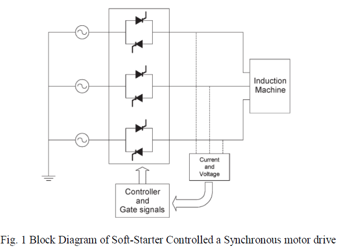
| THD is elevated. When the load is vacuous the soft starter method is dexterous. The feasibility of this thesis is that continuous Alternating current side input current in contrast to the conventional AC regulator where the input current is irregular. The major improvement with this scheme is the input current happens to be discontinuous continuous ac side within input current in contrast to the conventional ac regulator where. This in turn improves the transient response. This method mends the execution of the motor by dislodging the supply frequency torque pulsation. Block diagram of split phase induction motor with soft starter is shown in fig. |
 |
VERIABLE SPEED DRIVE |
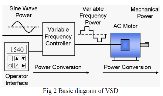
| Variable speed ac drives are used in ever-increasing numbers because of their well-known benefits for energy efficiency and for flexible control of processes and machinery using low-cost readily available maintenance free ac motors. Advances in solid state power conversion devices have opened up new field of application for ac machines to variable speed drive applications where formally only dc motors where practicalWith the recent advances in power electronics (bipolar transistor, inverter grade thyristor, GTO thyristor, IGBT etc.) and miniaturization/mass production of control electronics (development of VLSI technology and microprocessor based digital control systems), variable frequency and variable voltage (V.V.V.F) a.c motors drives have come into increased use in various industrial applications. |
 |
AC VOLTAGE CONTROLLER |
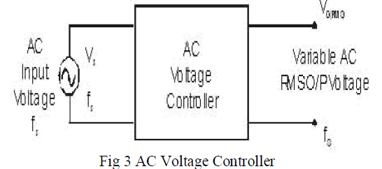
| AC voltage controllers (ac line voltage controllers) are employed to vary the RMS value of the alternating voltage applied to a load circuit by introducing Thyristors between the load and a constant voltage ac source. The RMS value of alternating voltage applied to a load circuit is controlled by controlling the triggering angle of the Thyristors in the ac voltage controller circuits. In phase control the Thyristors are used as switches to connect the load circuit to the input ac supply, for a part of every input cycle. That is the ac supply voltage is chopped using Thyristors during a part of each input cycle. The thyristor switch is turned on for a part of every half cycle, so that input supply voltage appears across the load and then turned off during the remaining part of input half cycle to disconnect the ac supply from the load. By controlling the phase angle or the trigger angle ‘α’ (delay angle), the output RMS voltage across the load can be controlled. The trigger delay angle ‘α’ is defined as the phase angle (the value of ωt) at which the thyristor turns on and the load current begins to flow. |
 |
DEVELOPMENT OF MATLAB/SIMULINK MODEL |
| Simulink is a software package which potentially viable you to model, simulate, and analyze systems whose outputs change over time. There are many many stages for the creation of any simulink model. Firstly , a block diagram is created by user, with the help of Simulink model user edited, that graphically depicts time-dependent mathematical relationships among the system's inputs, states, and then gated its outputs. The sample time of a block is a parameter that indicates when, during simulation, the block produces outputs and if appropriate, updates its internal state. Sample times can also be discrete, continuous, fixed in minor step, inherited, constant, variable, triggered, or asynchronous. A classic block diagram model of a dynamic system graphically consists of blocks and lines |
 |
THEORETICAL ANALYSIS |
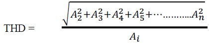
| Harmonic is a multiple integral multiple of fundamental frequency which disturb pure sinusoidal waveforms. Total Harmonic Distortion is the illustration of harmonic distorted current concerned with fundamental current. Harmonic distortion can be determined by following equations:- |
 |
 |
| These current equation conclude that by controlling firing angle can controlled the output current. |
SIMULINK MODEL OF SPLIT PHASE ASYNCHRONOUS MOTOR |
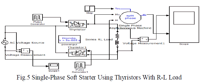
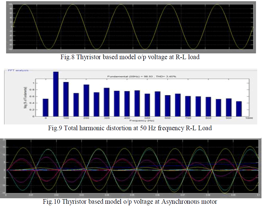
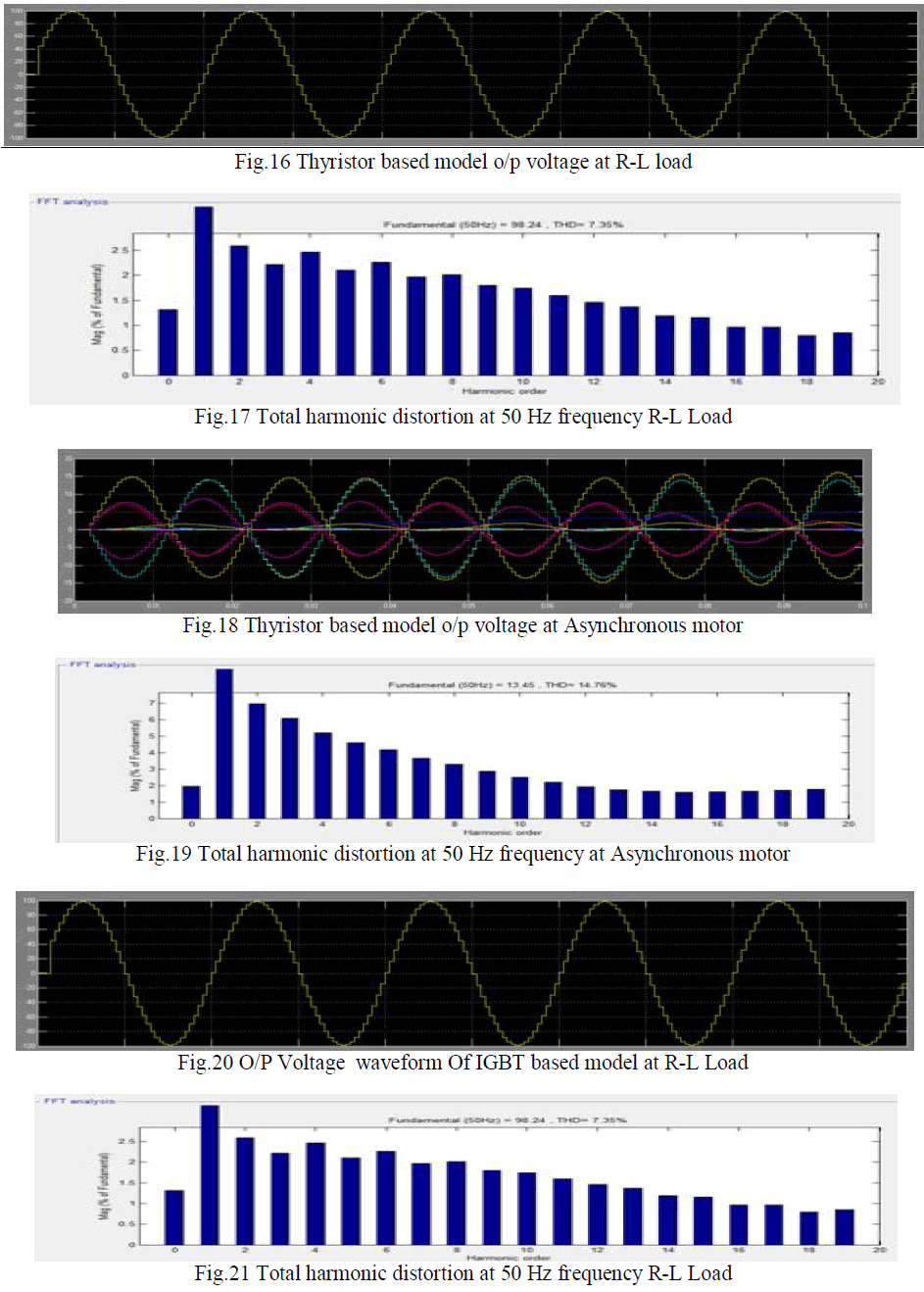
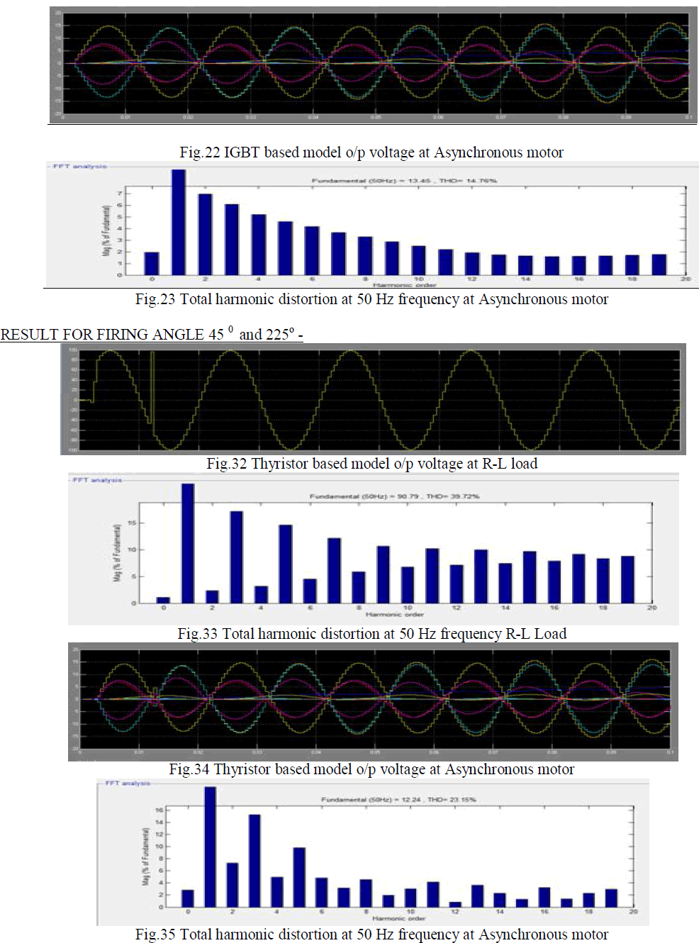
| This is the diagram of single-phase soft starter of single phase induction motor using Thyristors With R-L load. There is a ac voltage regulator connected with single phase ac supply. The regulator is equipped with thyristor. There are two triggering circuits connected with individual anti parallel thyristor pair. Now the next section is controlling unit which will controlled output of regulator circuit with respect to time. This stable output fed into the input of single phase induction motor and R-L load. For different values of firing angle there are their individual appropriate results and we can analyse the result on scope. |
 |
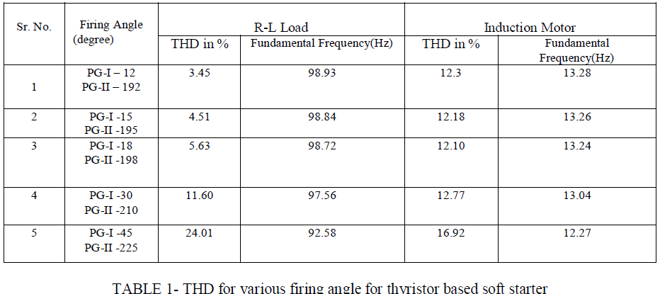
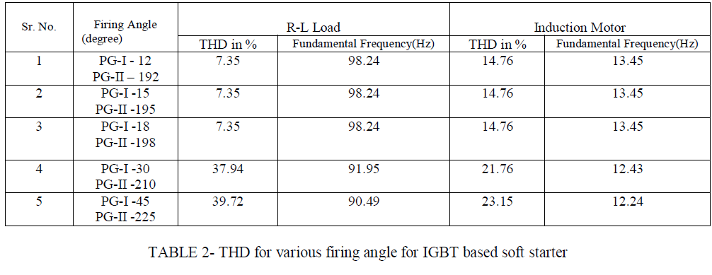
| This is the table of THD and fundamental frequency for various firing angle for thyristor based soft starter technique . Different firing angles have different THD as well as fundamental frequency for both R-L load and split phase induction motor. Following table will show the above fulfilment of soft starter techniques. |
 |
SIMULINK MODEL OF SPLIT PHASE ASYNCHRONOUS MOTOR USING IGBT |
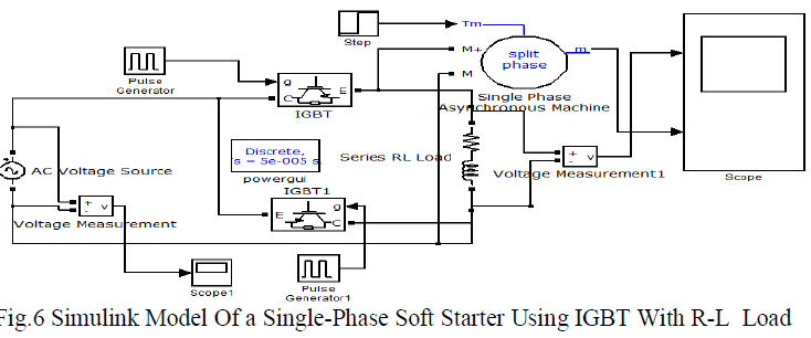
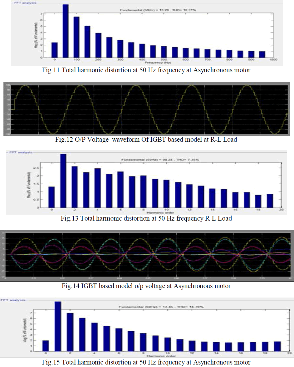
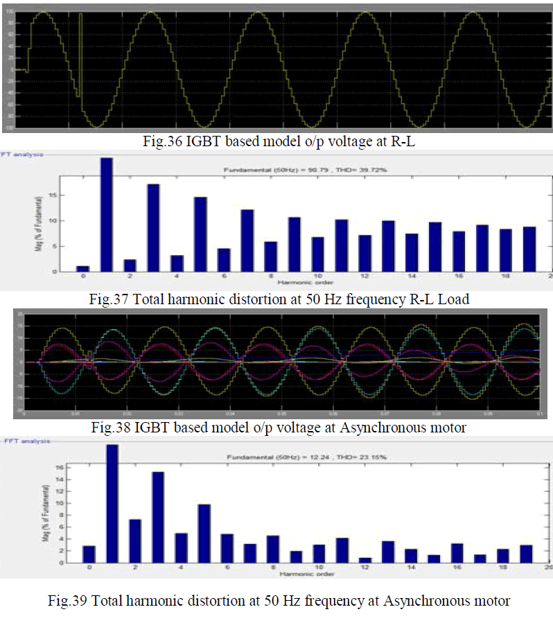
| This is the diagram of single-phase soft starter of single phase induction motor using IGBT With R-L load. There is a ac voltage regulator connected with single phase ac supply in which insulated gate bipolar transistor used. The regulator is equipped with IGBT. There are two triggering circuits connected with individual anti parallel IGBT pair. Now the next section is controlling unit which will controlled output of regulator circuit with respect to time. This stable output fed into the input of single phase induction motor and R-L load. For different values of firing angle there are their individual appropriate results and we can analyse the result on scope. |
 |
| This is the table of THD and fundamental frequency for various firing angle for insulated gate bipolar transistor based soft starter technique. Different firing angles have different THD as well as fundamental frequency for both R-L load and split phase induction motor. Following table will show the above fulfilment of soft starter techniques. |
 |
RESULT |
| Following are the results through simulation software for the respective firing angles which shows outputs of R-L load and split phase induction by waveforms between amplitude versus time. These results shows variations in outputs by changing firing angles with respect to time. |
| RESULT FOR FIRING ANGLE 12 ° and 192° - |
 |
 |
| RESULT FOR FIRING ANGLE 18° and 198° – |
 |
 |
 |
CONCLUSION |
| The paper analyze the performance of induction motor drive supplied from a variable voltage soft starter individually for thyristor and IGBT. This analysis conclude that when the firing angle gradually increases fundamental frequency decreases and THD increases. It is also concluded that with increasing firing angle, motor fails in critical cases. For same firing angle R-L load’s THD and fundamental frequency have higher value as compare to asynchronous motor THD and fundamental frequency. It is also concluded for same firing angle thyristor based soft starting gives low THD and high fundamental frequency as compare to IGBT based soft starting. As IGBTs requires filters to be used as power switch, large amount of distortion cab be observed in the input voltage which results in drive system instability, we set firing angle is set at its minimum value for reducing fluctuation and THD. |
References |
|