ISSN ONLINE(2278-8875) PRINT (2320-3765)
ISSN ONLINE(2278-8875) PRINT (2320-3765)
Siji Chacko1, Dr.Jaimol Thomas2
|
| Related article at Pubmed, Scholar Google |
Visit for more related articles at International Journal of Advanced Research in Electrical, Electronics and Instrumentation Engineering
Multilevel inverters got a lot of attention in recent years because its ability to generate staircase waveform which is more close to pure sinusoidal waveform. It has lot of applications in industries, FACTS devices, vehicle propulsion etc where power quality is more important. Instead of using higher rating semiconductor devices it uses some combinations of small rating semiconductor devices. It has several advantages such as less THD (Total Harmonic Distortion), reduced Electro Magnetic Interference (EMI), lower switching stresses and increased voltage capability. In this paper reversing voltage type multilevel inverter is modelled and THD analyses with different loads are done. The multilevel inverter used in this paper has two parts; one operated at high frequency (Level generation part) and other operated at line frequency (polarity generation part). The switching loss can be reduced to some extend by the use of polarity generation part. These types of inverters are appropriate choice for all type of loads and resultant THD with each type of loads are analysed. Simulations has been carried out in MATLAB/SIMULINK
Keywords |
| Electro Magnetic Interference, FACTS, Total Harmonic Distortion, MATLAB |
| Conventional transformer with multilevel inverter, H-bridge modules are connected to single dc source in parallel and secondary of single phase transformers are connected in series. But in [4] primary of three phase transformers connected to H bridge secondary is connected in series. But it is not suitable for variable frequency application. In [5] and [6], the multilevel output is generated with a multi winding transformer. But, the design and manufacturing of a multi winding transformer are difficult and costly for high power applications |
| This paper introduces an RV topology which uses less number of components that is mainly switches and its associated gate drives. One part works at fundamental frequency so the losses also reduced. It requires lesser number of carrier signals which reduces the complexity of control circuitary. |
MULTILEVEL INVERTER |
| Multilevel inverters have different topologies. Main topologies are diode clamped type, flying capacitor type and cascaded H bridge type [7]. |
A. Proposed Multilevel Inverter |
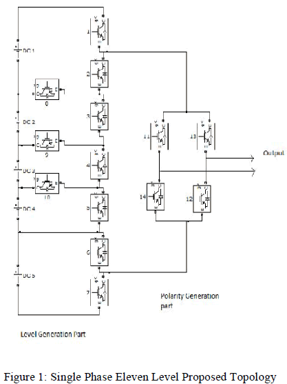
| In conventional multilevel topologies, the power semiconductor switches are combined to produce an output in positive and negative polarities. In this topology there is no need to utilize all the switches for generating bipolar levels. |
| This topology separates the output voltage into two parts. One part is called level generation part and is responsible for level generating in positive polarity. Level generation part requires high frequency switches to generate the required levels. The other part is named polarity generation part and is responsible for generating the polarity of the output voltage. This part is the low-frequency part operating at line frequency. |
| Fig.1 shows Schematic diagram of a single phase eleven levels reverse voltage topology. This topology easily extends to higher voltage levels by adding the middle stage. To the H-Bridge we add each stage according to the number of levels. So it’s called advanced H-bridge type. This topology is modular and can be easily increased to higher voltage levels by duplicating the middle stage. |
 |
| This requires fewer switches in comparison to conventional inverters. It is also applied to three phase application. Isolated DC source are needed. It just requires half of the conventional carriers for SPWM controller. SPWM for Eleven-level conventional converters consists of ten carriers, but here, five carriers are needed. The reason is that the multilevel converter works only in positive polarity. To generate polarity, the positive voltage is fed to the full bridge. |
| Multilevel inverter control is implemented using reduced number of carriers, which is a great improvement. Proposed topology does not need fast switches for the polarity generation part. |
A. Modes of Operation |
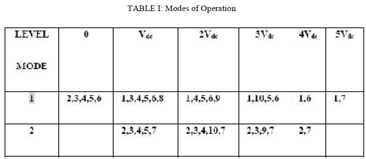
| There are ten possible switching patterns to control the multilevel inverter, shown in Table 1. In order to avoid unwanted voltage levels, the switching modes should be selected so that the switching transitions become minimal during each mode transfer. This will minimize switching power dissipation |
 |
CONTROL STRATEGY |
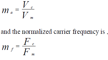
| The carrier based PWM technique fulfils the on and off states of the switches by comparing a modulating signal Vm (sinusoidal) and a triangular waveform Vc (carrier signal). The modulating signal is a sinusoidal at frequency Fm and amplitude Vm and the carrier signal is at frequency Fc and amplitude Vc. This is the sinusoidal PWM (SPWM) method. |
| The modulation index is defined as, |
 |
| In this topology phase deposition-SPWM is adopted for its simplicity and the carriers are in phase with each other. Here phase deposition SPWM is used for driving the high frequency switches and low frequency polarity generation part drive signals are generated with the line frequency (50Hz), and they only changes at zero-voltage crossings. Conventional cascaded multilevel inverter uses (n-1) carriers and in the proposed topology carriers for an n level inverter is (n-1) / 2 |
NUMBER OF COMPONENTS |
| One of the main advantages of this topology is that it requires less high-switching frequency components. The reliability of a system is indirectly proportional to the number of its components. As the number of high-frequency switches is decreased, the reliability of the converter is increased. 2(N-1) switching devices are required for an N level conventional cascaded H bridge multilevel inverter where N is the number of the output voltage level. In this topology only ((N-1) +4) switches are needed for an N level inverter. It can clearly be mentioned that the number of components of this topology is lower than that of other topologies and it will decrease tremendously with higher voltage levels. Switches in the full bridge converter are switched at line frequency. |
METHODOLOGY |
| The eleven-level inverter whose output voltage has eleven values: zero,Vdc, 2Vdc, 3Vdc, 4Vdc, 5Vdc ,- Vdc, -2Vdc, -3 Vdc, -4Vdc, -5Vdc so called an eleven level PWM inverter. This inverter can reduce the harmonic components and the switching stress. Operational principles and switching functions are analyzed. The proposed inverter improves the dynamic performances. PWM signals are generated using PD-SPWM technique. Output voltage obtained was 500 Vpp and 4 KHz is the switching frequency. DC power supplies are adjusted to 50 V |
SIMULATION RESULTS |
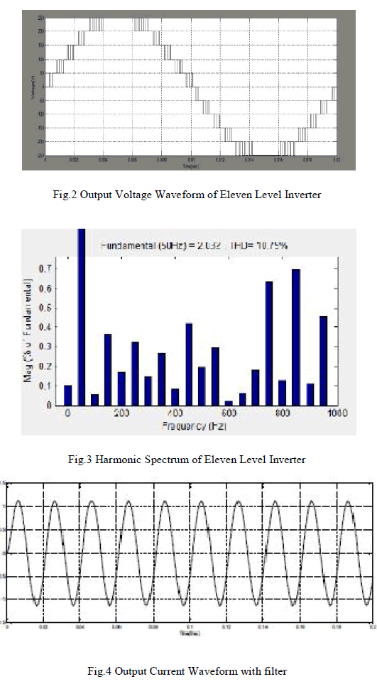
| Simulation of proposed multilevel inverter (eleven level) is performed using MATLAB. The output waveforms of these are given. All input dc sources are equal. The waveform of proposed multilevel inverter with resistive load is shown in Fig 2. The resulting THD was 10.79 % . |
| The harmonic spectrum is shown in Fig .3, With a small size filter the THD of output brings to IEEE519 std, for this an inductance of 5 mH an capacitance of 2 μF are used. Current waveforms after using filter is shown in Fig.4 Table.2 shows the number of switches and carrier signals used in cascaded H-bridge and the proposed topology. It should be noted that proposed topology uses less number of switches and carrier signals. |
 |
 |
| The THD analysis of these three levels with various loads are conducted and obtained results are shown in Table .3. It shows with increase in number of levels current THD reduces. Inverters with RL(R = 124,L=182 mH) load shows a good improvement in THD than inverters with R load. It is pointed out that the load inductance plays an important role in shaping good quality current waveform. By using filter current THD further get reduced. |
 |
CONCLUSION |
| Multilevel inverters have been used in many industrial applications like HVDC, FACTS, PV systems, UPS and Industrial drive applications. In the proposed topology switching operations are separated into high and low frequency parts. Instead of using other inverter topology, proposed topology is better for all these applications because it has less control complexities and cost. It also reduces the THD of output to a great extend thus reduces the size of filter too. As the level increases THD of Output reduces. It can be used in applications where quality of output is primary need. The simulation results show the improvement of quality of voltage waveform as level increases. Simulation results with various loads were discussed. All types of loads are works well with this advanced H-Bridge topology. |
References |
|