International Journal of Advanced Research in Electrical, Electronics and Instrumentation Engineering
ISSN ONLINE(2278-8875) PRINT (2320-3765)
ISSN ONLINE(2278-8875) PRINT (2320-3765)
Riya Philip1, Reshmi V2
|
| Related article at Pubmed, Scholar Google |
Visit for more related articles at International Journal of Advanced Research in Electrical, Electronics and Instrumentation Engineering
Nowadays, harmonic distortions and low Power Factor (PF) are serious problems that gained more importance in power electronics area. In this paper, Three phase PFC and harmonic mitigation using Active Power Filter (APF) topology and Buck-Boost circuit topology are realized. Here the nonlinear load considered is a 12 pulse diode bridge rectifier. First, harmonic mitigation and power factor correction is done by using a shunt Active Power Filter. Here, the strategy used to extract the three phase reference currents are based on the synchronous reference frame method and the control used is hysteresis control. Then another method of Buck-Boost converter topology for harmonic mitigation and power factor correction is also analyzed. Here the control is in such a way that to profile the rectifier output current to be triangular which results in low ac side harmonics. The switching frequency is set to 10 kHz. The simulation analyses are carried out in Matlab/Simulink software. The effect of APF and Buck-Boost circuit on PF and the sinusoidal nature of line current are analyzed by the simulation results.
Keywords |
| Power Factor Correction (PFC), Buck-Boost Circuit Topology, Active power filter, Current shaping control |
INTRODUCTION |
| Power quality has become a critical issue in industries and sensitive load centers. Nowadays, power electronic appliances are used widely in industrial, commercial and consumer environment. These appliances create a lot of power quality problems in power system. The problems of voltage sags, low power factor, spikes, electrical noise, harmonic distortion etc are some of the common power quality problems. The main issues that affect the quality of voltage and current waveforms are presence of harmonics and low power factor in power system. A circuit topology that can improve PF and mitigate harmonics is essential especially for nonlinear loads. |
| Non linear loads usually create harmonics and low power factor, and distort the sinusoidal current waveform to some other form. The presence of harmonics (both current and voltage) is viewed as pollution affecting the operation of power systems. Harmonics can cause malfunction of sensitive equipments including overheating of transformers and wiring, nuisance breaker trips, and reduced power factor. High levels of power system harmonics can create voltage distortion and reductions in ac motor efficiency. The presence of harmonics increases the apparent power that must be delivered, therefore lowering the power factor. |
| In fact, a low power factor reduces the power available from the utility grid. The loads having low PF will draw more current than the loads having high PF for the same amount of power. When low power factor is not corrected, the utility must provide the nonworking reactive power in addition to the working active power. This results in the use of larger generators, transformers, bus bars, wires, and other distribution system devices that otherwise would not be necessary. So improving the power factor and mitigation of harmonics in power system is very essential. |
II. LITERATURE REVIEW |
| The PFC circuit basically shapes the input voltage waveform in phase with input current waveform. A variety of circuit topologies and control methods have been developed for the harmonic mitigation and PFC application. Conventionally there are mainly two types of harmonic mitigation methods are used [1]. |
A. Passive Filters |
| Conventionally, passive filters have been used to eliminate the line current harmonics and to improve the power factor. Passive filters are the most simple and reliable means of harmonic mitigation. They were robust and easy to install. Conventional passive filters consist of inductance, capacitance, and resistance elements configured and tuned to control harmonics. But, they do not always respond correctly to the dynamics of the power systems. They have many disadvantages such as fixed compensation, large size and resonance problems. Passive filters are known to cause resonance, thus affecting the stability of the power distribution systems. Frequency variation of the power distribution system and tolerances in component values affect the passive filtering characteristics. So passive filters might not be able to meet the harmonic limitations of international standards. This may required a retrofit of new filters [2]. |
B. Active Power Filters |
| Remarkable progress in power electronics had raised the interest in Active Power Filters for harmonic mitigation. APFs performances are independent of the power distribution system properties. Figure 1 shows the basic block diagram of active power filter. The working of active power filter consists of mainly three stages. They are: Signal conditioning, Derivation of compensating signal and Generation of gating signal. |
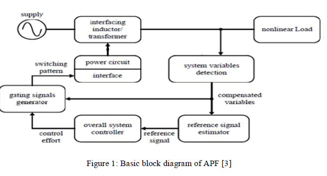 |
| Signal conditioning refers to the detection or sensing of harmonics in the power distribution line. As shown in Figure 1, the reference signal estimation is initiated through the detection of essential voltage/current signals sensed by using potential transformers, current transformers etc. The next stage is the derivation of compensating signal from the disrupted wave consists of both fundamental wave and the harmonic content. It can be done by different methods like Fourier transformation method, Instantaneous Reactive Power Theorem, Synchronous Reference Frame Theorem, Synchronous Detection Theorem etc. The third stage is the generation of gating signal for harmonic suppression. So many control techniques like space Vector PWM, repetitive control, hysteresis current control, dead beat control, sliding mode control, fuzzy control etc have been introduced and applied to various configurations of active power filters [3][4]. |
III. PFC AND HARMONIC MITIGATION BY USING APF |
| This section describes the compensation technique of a Shunt APF with Synchronous Reference Frame Method (SRF theory) and Hysterisis band control which allows both dynamic power factor correction and harmonic mitigation. Figure 2 shows the compensation principle of a three phase shunt active power filter with a 12 pulse rectifier as nonlinear load. The source is a balanced Y-connected three phase voltage source where the phase voltages are Va , Vb and Vc, while the nonlinear loads connected to each phase produces nonlinear load currents ia, ib and ic . The supply is given to the two 6 pulse rectifiers through a transformer whose primary is delta connected and secondary have two windings-star and delta, so as to provide 30° phase shift to each supply [5]. |
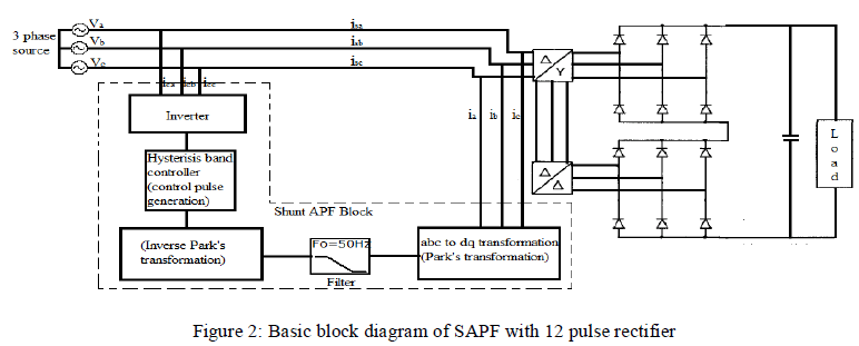 |
| When the SAPF block is not operating the nonlinear load current are themselves the line currents isa, isb and isc, which causes degradation in power factor and introduces harmonic distortion. When the SAPF block is operating, it injects currents ica, icb and icc equal in magnitude but in phase opposition to harmonic current in each of the lines. This compensates the harmonic distortion and makes the source current balanced and sinusoidal while the load current remains nonlinear. The Shunt APF block is basically divided into three parts. The first part consists of reference signal generation by using Park's transformation. The second part is a control block which does necessary computations and operations to generate the control pulses. This reference is fed to the IGBT based Voltage Source Inverter (VSI). A dc capacitor usually works as the source of power for the VSI. According to the switching pulses the inverter provides current waveforms that are opposite in phase to the harmonic waves. They are injected to the system using coupling inductors or transformers which in turn cancel out the effect of harmonic waves from the source current [5]. |
IV. PFC AND HARMONIC MITIGATION BY USING BUCK-BOOST TOPOLOGY |
| A new method of PFC and harmonic mitigation is proposed in [6] by authors Lukic and Bhai using Buck-Boost converter topology. The 3 phase supply is rectified by 12 pulse diode bridge rectifier and the output is given to a Buck- Boost converter. A new method of profiling the dc side rectifier current to triangular waveforms and thus shapes the input source current as sinusoidal is used here. Current sources are placed in parallel with each six pulse rectifier bridge which is used to inject current and shape the rectifier output current. The method is simple to implement and makes use of standard series connected isolated gate bipolar transistor or metal oxide semiconductor field effect transistor (MOSFET) modules. The property of the resulting current sources is that they are able to deliver power to the load, allowing for the integration of an energy storage system on the dc side. The VA rating required to profile the current is reduced by a proper choice of the dc side LC filter parameters. The output current is shaped here by the proper control signal generation to the MOSFET switches of the Buck-Boost converters. The exact shape of rectifier output current that results in complete elimination of ac input current harmonics is found to be triangular waveform. Its Fourier series expansion helps in quite simple calculation of harmonics in ac side line current [6]. |
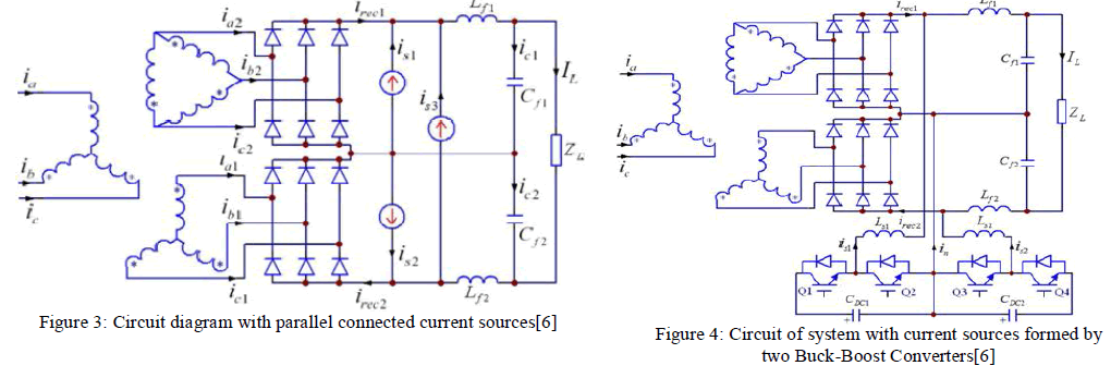 |
| The three current sources are inserted into the circuit as shown in Figure 3. The current sources shown in the figure is1, is2 and is3 are used for current shaping control. The two current sources (is1 and is2) in parallel with each rectifier are used to shape the rectifier currents irec1 and irec2 in order to eliminate the ac side harmonics. The third current source is3 is used to inject active power from an energy storage system. The hardware implementation of the three current sources shown in Figure 3 is shown in Figure 4. The current sources are implemented by using two cascaded buck and boost converters which provide two independent currents is1 and is2. The third current is3 results from a combination of is1 and is2 (is3 = is1 - is2). The dc bus of the cascaded buck and boost converter can be supplied by a capacitor bank same as in active filter designs. |
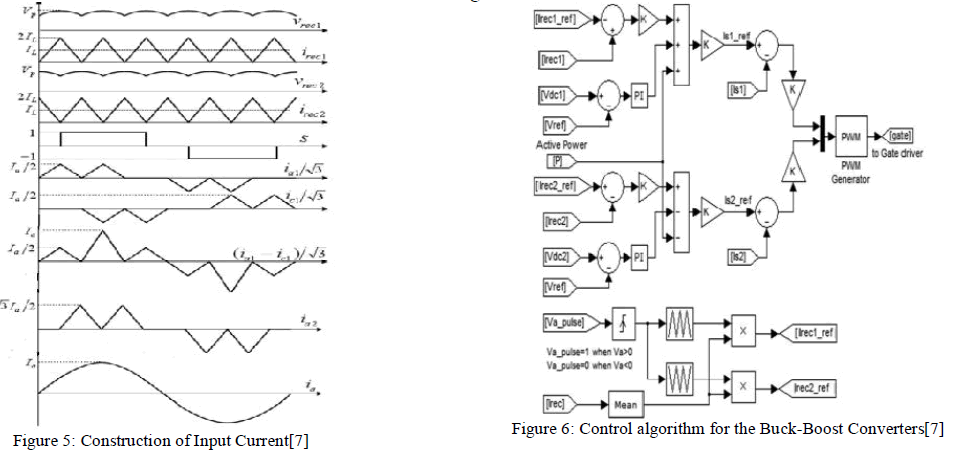
| The construction of input current by shaping rectifier output current is as shown in as shown in Figure 5. If we can shape irec1 and irec2 as triangular waveforms, then according to Fourier transform, considering a particular time period, the equation for input current ia can be given as, |
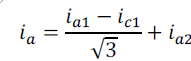 |
| Then the construction of ia from ia1, ic1 and ia2 is as shown in Figure 5. |
 |
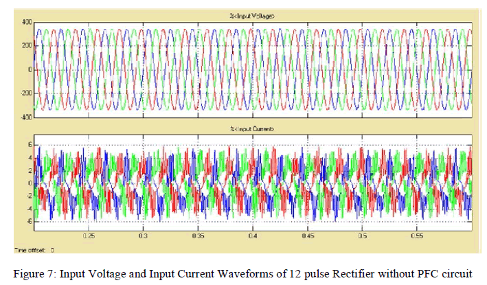
| Figure 6 describes the proposed control strategy for the switches shown in Figure 4. Similar to active power filter control, a simple proportional controller is used to act on the error between the references is1ref and is2ref and the inductor currents is1 and is2. |
| The current references for the two inductors is1ref and is2ref are made up of three components. The first component ensures the tracking of the triangular reference. The desired triangular references irec1ref and irec2ref are generated by multiplying the averaged rectifier output current (Irec1 and Irec2) and the triangular reference which is synchronized with the line voltage. The dynamics of the averaging can be fairly slow, since the result of a mismatch between the estimated and actual values of IL simply results in real power injection/absorption by current source into the load during the transient. The second component balances the voltages of the energy storage elements (batteries or capacitors) that supply the current source. Since the voltage sources represent dc signals with fairly large time constants, a proportional-integral control is used to ensure zero steady state error. The third component is used to inject active power into the dc bus from the energy source. Overall, the control is much simpler than that of the ac side active power filters [6][7]. |
V. SIMULATION ANALYSIS |
| Software simulation of the power factor correction circuit with three phase diode bridge rectifier is done in MATLAB/Simulink. In the sample circuit of the considered system, a three phase twelve pulse diode bridge rectifier having two six pulse diode bridges is taken as the non linear load. The input supply is 415V and the switching frequency is set to 10kHz. |
A. Simulink Model of Twelve Pulse Diode Bridge Rectifier |
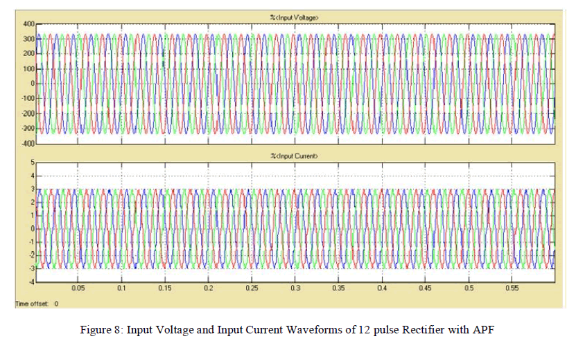
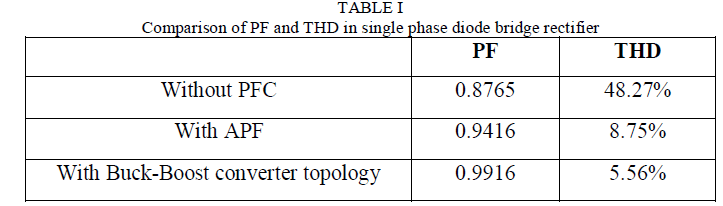
| The three phase 12 pulse diode bridge rectifier is simulated without any PFC circuits in MATLAB. The input power factor of the converter is displayed as 0.8765 and THD is measured as 48.27%. The converter input source voltage and current waveforms with output capacitor filter are as shown in Figure 7. |
 |
B. Simulink Model of 12 Pulse Rectifier with APF |
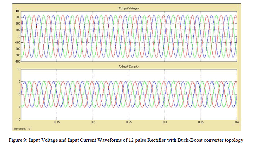
| The mean power factor displayed here is 0.9416. The THD of the circuit is measured as 8.75%. The input current and voltage waveforms of the 12 pulse rectifier with APF are as shown as Figure 8. |
 |
C. Simulink Model of 12 Pulse Rectifier with Buck-Boost Converter Topology |
| The simulation model of 12 pulse diode bridge rectifier with Buck-Boost converter topology is simulated. The power factor of the system is shown as 0.9916. And the THD is measured as 5.56%. The input voltage and current waveforms of 12 pulse diode rectifier with Buck-Boost converter topology is as shown in Figure 9. |
 |
D. Comparison of Simulation Results |
| From the Table 1 below it can be summarized that the PFC and harmonic mitigation can be effectively done by using Buck-Boost converter topology with current shaping control. |
 |
VI. CONCLUSION |
| Traditional diode rectifiers are commonly used for AC to DC power conversion. In three phase systems, generally twelve pulse rectifiers are widely used. These electrical equipments generate harmonic waves and suffer low power factor. Now converters with power factor correction have received greater attention due to improved power factor and low harmonics. The Buck-Boost PFC topology has the ability to regulate the output voltage to a desired value by varying the duty ratio. Twelve pulse diode bridge rectifier without PFC circuits and with PFC circuits are simulated in MATLAB/Simulink. PFC circuit with Buck-Boost converter topology controls the input power factor very much better than the PFC circuit with APF control. The power factor is improved to a value 0.9916 and the THD is reduced to 5.56%. So Buck-Boost converter topology can be considered as a good choice for harmonic mitigation and power factor correction. |
References |
|