ISSN ONLINE(2278-8875) PRINT (2320-3765)
ISSN ONLINE(2278-8875) PRINT (2320-3765)
| K.Subbulakshmi Dept of ECE, Bharath University, Chennai.,Tamil Nadu, India |
| Related article at Pubmed, Scholar Google |
Visit for more related articles at International Journal of Advanced Research in Electrical, Electronics and Instrumentation Engineering
Almost two decades of research on unidirectional three-phase multilevel boost-type pulse width modulation (PWM) rectifiers have shown the benefits of employing this technology to comply with power quality standards while assuring high efficiency and low volume and weight. However, the unidirectional topologies directly derived from the conventional three-level bidirectional converters, such as the neutral point clamped (NPC), the flying capacitor and the cascaded H-bridge converters have not been properly analyzed. This letter introduces some of the unidirectional topologies that arise from the inspection of the widespread conventional bidirectional converters. Special emphasis is put in the analysis of the NPC-based three-phase/-level PWM rectifier operating as power factor corrector.
Keywords |
| AC–DC power conversion, circuit topology, converters, power electronics, pulse width modulated power converters. |
INTRODUCTION |
| The unidirectional three-phase/-level boost-type PWM rectifiers are able to generate voltages with instantaneous average values that approach pure sinusoidal voltages at one end of the input inductors, from where the input currents flow in phase with the power grid phase voltages. Therefore, high-quality current waveforms can be generated. The three-level operation allows the voltage steps to be lower than those found in two-level topologies, from where lower harmonic contents are observed. Thus, smaller input filters are allowed. In addition, the voltage across the semiconductors is, in theory, limited to half of what is typical in two-level topologies. This feature enables the use of semiconductors with lower voltage ratings, thus, with lower voltage drops for the same current ratings and reduces the switched voltages. With this, both, conduction and switching losses can be reduced. The overall result is that smaller/lighter cooling systems and passive components are employed when compared to two-level systems. However, modulation, control and voltage balancing challenges arise with the three-leveltopologies and make their design more complex, increasing the efforts in control hardware. |
II.UNIDIRECTIONAL MULTILEVEL TOPOLOGIES |
| Unidirectional multilevel PWM rectifiers based on the widespread bidirectional multilevel converters known as the NPC, the flying capacitor (FC) and the symmetric cascaded H-bridge. |
A.UNIDIRECTIONAL FC-BASED PWM RECTIFIER |
| One leg of a three-level FC converter is shown in Fig. 1(a), which allows for bidirectional power flow. Fig. 1(b) takes into consideration an unidirectional power flow from a current source connected at a to the output voltage source between pand n and shows that switches Sp,Aand SA,nare not required for this operation mode. Another equivalent topological variation would be to exclude SA,pand Sn,A. Fig. 1(c) Leg of the FC-based PWM rectifier topology, suffices for unidirectional operation as shown in Table1. |
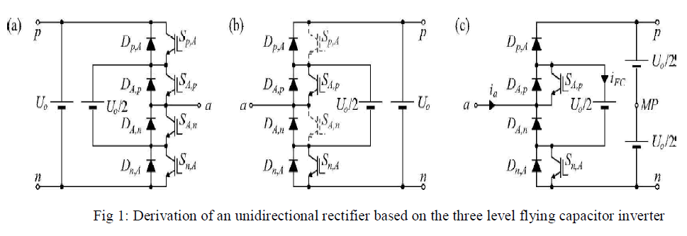 |
| The resulting topology presents the same characteristics as bidirectional one, except from the fact that the current through the flying capacitor i FC is only positive for ia>0 and negative for ia<0. Table 1: Switching states for leg a for the flying capacitor-based Topology |
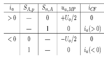 |
| Therefore, the balancing strategy of such capacitor should consider this fact. A drawback of the three phase topology is the requirement to balance more than two dc voltages. Conduction losses are expected to be low, since a low number of semiconductors are in series with the paths for the switched currents. |
B.SYMMETRIC CASCADED H-BRIDGE-BASED PWM RECTIFIER |
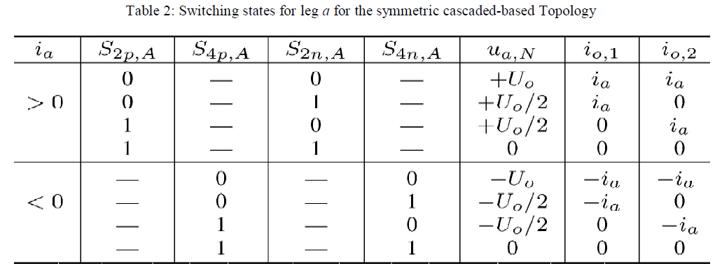
| Another widespread multilevel topology is the symmetric cascaded H-bridge inverter. It is also possible to generate a unidirectional version based on a leg of the original topology as shown in Fig. 2 and in Table 2, where two of the upper or lower switches can be excluded from each H-bridge cell. This leads to half of the number of turn-off switches when compared to the bidirectional version. |
| As the original topology, the unidirectional circuit requires isolated dc outputs that must be controlled. The main characteristics remain, so that the frequency at the input can be twice the switching frequency; any number of such cells can be stacked, so that this topology is highly modular, and, low conduction losses are expected. |
 |
 |
C. NEUTRAL POINT DIODE CLAMPED-BASED PWM RECTIFIER |
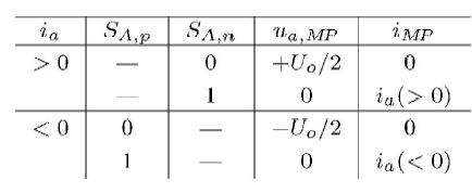
| The neutral point clamped inverter is a bidirectional three-level PWM topology, which is widely employed in high power conversion. Fig. 3(a) shows one leg of such inverter. Table 3:Switching states for leg a for the npc-based topology in dependency of the input current direction |
 |
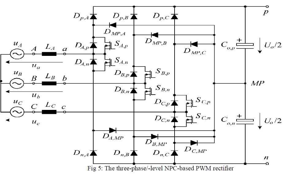
| The dc-link is split into two equal voltages Uo/2 that limit the voltage across the switches Sp,A, SA,p, SA,n, and Sn,Athrough the clamping diodes DMP,A and DA,MP . |
| Point a shall be connected to a current source, which is typically an interfacing inductor or an electrical machine. Inverting the drawing direction and considering the power flowing uniquely into the dc-link as shown in Fig. 3(b) causes no current to flow through switches Sp,Aand Sn,A. Therefore, for unidirectional rectifier operation the NPC topology can be reduced to the circuit shown in Fig. 3(c). |
 |
III.PFC OPERATION OF A THREE-PHASE/-LEVEL NPC-BASED PWM RECTIFIER |
| The NPC-based rectifier shown in Fig. 4. It can be seen that diodes DA,p and Dp,Aconduct the input current when it is positive and switch SA,nis switched off. When the current is reversed and switch SA,pis on, the current flows through SA,pand DMP,A . The other stages are complementary to these ones. It can also be seen that if MOSFETs are employed, they can be switched on whenever the body diodes conduct in order to reduce the conduction losses in the diodes. |
 |
| For generating the input voltages at the input terminals, this topology presents the same voltage vectors as the topologies as well as the same characteristics regarding the balancing of the output voltages. Thus, all modulation and control schemes that have been proposed for these topologies can be directly employed here, including the balancing of the output voltages through the injection of a zero-sequence component in the current control signals. |
A. STRESSES IN THE SEMICONDUCTORS |
| Considering the circuit in Fig. 5, the switched voltages across all semiconductors are clamped to the voltages Uo/2 across the dc-link capacitors Co,pand Co,n.Considering PFC operation and defining the input currents |
 |
| The modulation index M is defined as M = 2Upk/Uo. |
| The average and rms currents are as defined in Table 4. |
|
|
 |
IV.SIMULATION RESULT |
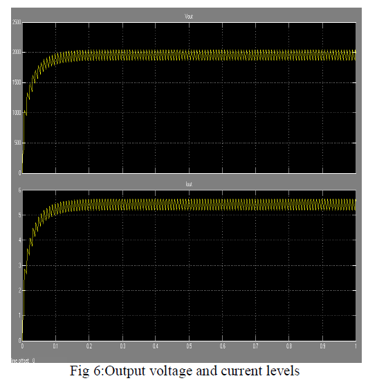
| The voltage balance control loop acts to adjust the dc output voltages as observed for an initial unbalance of 20%.Figure 6 shows the output voltage and current waveforms. |
 |
V.CONCLUSIONS |
| The unidirectional topologies directly derived from three conventional bidirectional converters have been developed for unidirectional power flow. The FC and the symmetric H-bridge topologies require a higher control effort, since they require more dc voltages to be stabilized. The unidirectional NPC-based topology operating as PFC rectifier was analyzed in detail. It showed similar characteristics to more widespread three-level topologies and is an interesting alternative as a three-phase PFC rectifier. |
References |
|