ISSN ONLINE(2278-8875) PRINT (2320-3765)
ISSN ONLINE(2278-8875) PRINT (2320-3765)
Ramesh Babu.Deva1, Arundhati.B2, Alice mary.K3
|
| Related article at Pubmed, Scholar Google |
Visit for more related articles at International Journal of Advanced Research in Electrical, Electronics and Instrumentation Engineering
The significant drawback of PMLSM is thrust ripples, which is mainly generated by the detent force caused by the interaction of the permanent magnet and iron core without input current in armature winding. It is the function of mover position relative to the stator. This will deteriorate the performance of the drive system in high precision applications. This paper focus on the thrust ripples reduction. To minimize the thrust ripples and realize the high-precision control, the components of thrust ripples are extracted first and then compensate with PI and IMC (Internal Model Control) controller.
Keywords |
| permanent magnet linear synchronous motors, field oriented control, ripple compensation, curve fitting, IMC controller. |
INTRODUCTION |
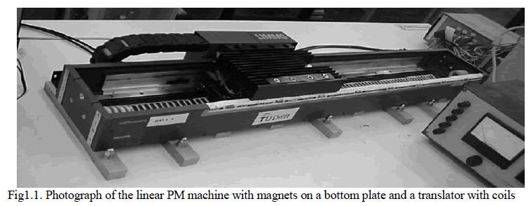
| The Permanent magnet linear synchronous machine (PMLSM) is more and more used in the field of factory automation, such as in positioning and robotic application and translation system including horizontal, slanted and vertical translation. In long stroke transportation the segment primary PMLSM is noticed in order to save the cost of materials, manufacturing time, convenient to be maintained and adjusted, increase loss and faults [10]. The main benefits of PMLSMs include the high force density in the air-gap, a rapid dynamic response, low thermal losses and simple structure. However, PMLSM presents an important drawback due to the detent force. Detent force makes thrust ripple producing both vibration and noise of the motor and deteriorating the control characteristics of speed control at low speed as well as of position control. The effects of thrust ripple are particularly undesirable in some demanding motion control and machine tool applications [3]. They lead to speed oscillations, which cause deterioration in the performance. The thrust ripples change periodically as the mover advances during its motion. |
 |
| Detent force is developed from the attractive force in the thrust-direction between the armature core and permanent magnet. In PMLSM, there are two potential causes of the detent force, resulting from the slotting and the finite length of the iron-cored armature, named the end component and slot component respectively, independent of the primary winding current. In general, the end component of the machine is larger than the slot component [5, 6]. |
| Section I gives the introduction about Permanent magnet linear synchronous motor with detent force. Section II is modelling of permanent magnet linear synchronous motor including detent force. Section III is used to describe about detent force in permanent magnet linear synchronous motor and derived detent force equation from curve fitting technique. Section IV Design of PI controller and IMC controller for compensating the undesired thrust ripples from permanent magnet linear synchronous motor. Section V simulation results. Section VI without detent force in permanent magnet linear synchronous motor with 5m/s and load thrust 10N simulation graphs. Section VII with detent force in permanent magnet linear synchronous motor with 5m/s and load thrust 10N simulation graphs. |
MODELLING OF PMLSM |
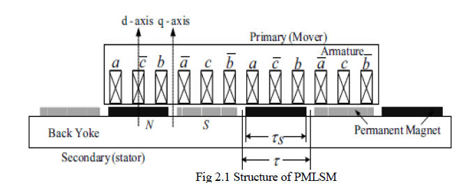
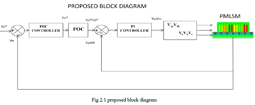
| PMLSMs may be classified into short primary type (long PM poles) and short secondary type (short PM poles) according to their structural features. Fig. 2.1 shows the basic structure of a short primary type PMLSM. There are alternant N-pole and Spole permanent magnets fixed on the stator (secondary) of the PMLSM, and the mover (primary) comprises the armature and windings [1]. The mover will move with the cable, which supplies power by a current-controlled pulse width modulated (PWM) voltage source inverter (VSI) to the PMLSM. |
 |
| The mathematical model of PMLSM is basically as same as the PM rotary motor. The modelling equations are derived based on the following assumptions. |
| a) The magnetic circuit is not saturated |
| b) No damper winding in the motor |
| c) Core loss is neglected |
| d) Back-EMF is sinusoidal |
| e) Magnets are surface mounted with a constant air gap. |
| The d-q voltage equations for PMLSM in mover reference frame are given by [7], |
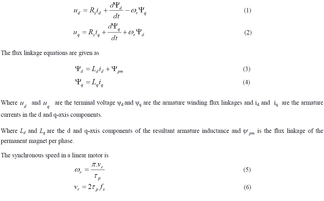 |
| Where p is pole pitch, r v is velocity of linear synchronous velocity. |
| The field oriented control (FOC) method that employs a force compensator and an online observer to compensate the detent force in order to obtain a stable output thrust from the PMLSM drive system. The d-axis current id is zero for the FOC method and the d and q-axis reluctances of a surface mounted PMLSM are same. Therefore, the electric thrust is given as follows: |
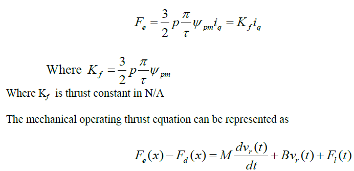 |
| Where M is the total mass of the mover; B, is the damping coefficient; vr, the mover mechanical velocity; Fd, the detent force and l F , is the external load thrust. |
 |
DETENT FORCE |
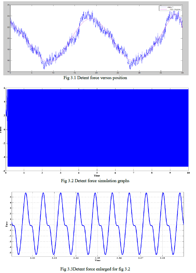
| The detent force can be divided into two components: One is the slot effect caused by the slotted iron core, the other is the end effect caused by the finite mover length. Detent force must be a periodical function, which contains two different wavelengths: one is of the pole pitch caused by the end effect, and the other is of the slot pitch caused by the slot effect. The detent force can be measured by moving the motor at a constant velocity and recording the current output of the driving amplifier versus time. Knowing the velocity and the motor’s force constant, force versus position can be plotted. Figure 3.1 shows the simulation plot using detent force and position values. This plot was created using a parker trilogy R7-1 linear motor [5]. This motor has a pole pitch of 40mm which leads to the periodic waveform shown. |
| From curve fitting technique the Detent force equation is |
 |
| This is the compensation function to counteract the thrust ripples. And the obtained graph is as shown in fig 3.2. Fig3.3 is enlarged figure for fig 3.2 |
 |
DESIGN OF CONTROLLER |
4.1 Design of IMC (internal model control) controller |
| The Internal Model Control (IMC) philosophy relies on the internal model principle, which states that control can be achieved only if the control system encapsulates either implicitly or explicitly, some representation of the process to be controlled. In particular, if the control scheme has been developed based on an exact model of the process, then perfect control is theoretically possible. |
| The open loop control strategy is shown below |
 |
| A control strategy, Gc(s), is used to control the process, Gp(s). Suppose ( ) ~ Gp s is a model of Gp(s).By setting Gc(s) has to be the inverse model of the process, |
 |
| Then it is clear that the output will always be equal to the set point. Notice that this ideal control performance is achieved without feedback. What this tells us that if we have complete knowledge about the process (as encapsulated in the process model) being controlled, we can achieve perfect control. It also tells us that feedback control is necessary only when knowledge about the process is inaccurate or incomplete. |
 |
SIMULATION RESULTS |
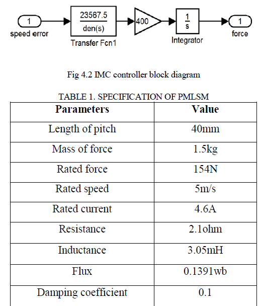
| In this paper, the IMC speed controller transfer function is |
 |
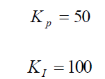
| PI current controller gain values are: |
 |
| For current controllers, |
 |
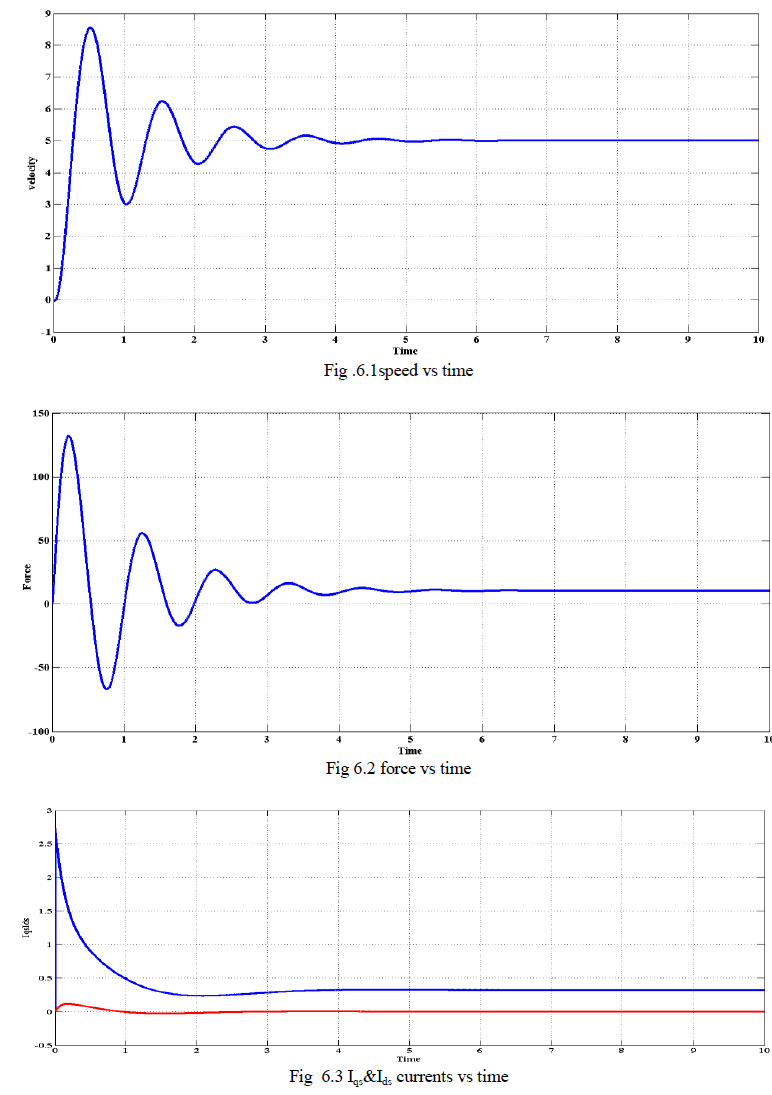
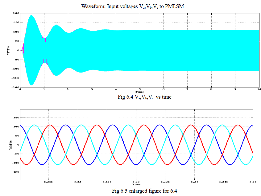
RATED SPEED 5(M/S) AND LOAD THRUST ïÿýïÿýïÿýïÿý = 10 COMMAND RESPONSES |
| In this case, the motor was taken into rated speed 5(m/s) and load thrust 10(N). We observed the speed, force and current respectively. |
 |
 |
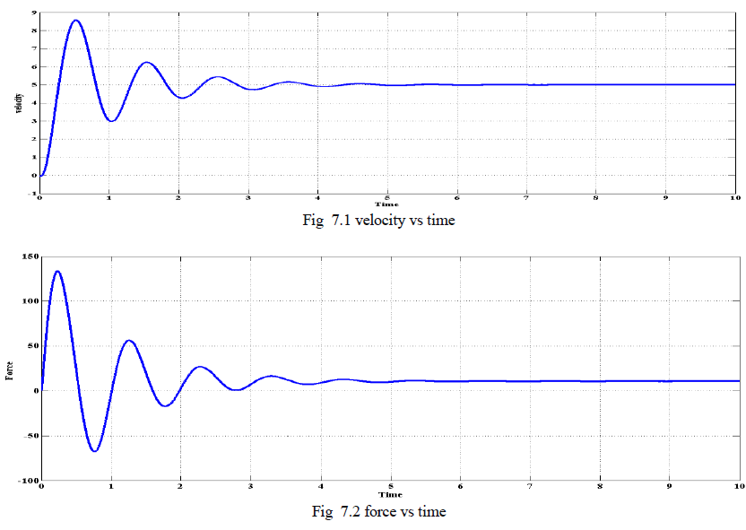
WITH DETENT FORCE RATED SPEED 5(M/S) AND LOAD THRUST Fl= 10 COMMAND RESPONSES |
| In this case, the permanent magnet linear synchronous motor included with detent force was taken into rated speed 5(m/s) and load thrust 10(N). We observed the speed, force and current respectively. |
 |
 |
CONCLUSION |
| This paper introduces a simple method to reduce the thrust ripples in permanent magnet linear synchronous motor (PMLSM) , which first extracts the thrust ripples from actual linear machine (parker trilogy R7-1 linear motor) and created detent force equation by using curve fitting technique and then compensated that detent force by using IMC and PI controllers. From the observed outputs we can conclude that though the detent forces are included in the machine, the IMC and PI controllers is working perfectly by tuning the thrust ripples in such a fashion that the outputs are achieved correctly. |
ACKNOWLEDGMENT |
| This work is supported by All India council of Technical Education (AICTE), New Delhi under research promotion scheme; file no 8023/RID/RPS-78/2010-2011 |
References |
|