ISSN ONLINE(2278-8875) PRINT (2320-3765)
ISSN ONLINE(2278-8875) PRINT (2320-3765)
Sneha Bhavsar1, Dr.Hina Chandwani2
|
| Related article at Pubmed, Scholar Google |
Visit for more related articles at International Journal of Advanced Research in Electrical, Electronics and Instrumentation Engineering
The matrix converter is an array of controlled semiconductor switches that connects directly the m-phase source to the n-phase load. The Matrix Converter (MC) evolved from the forced commutated cycloconverters and has been extensively investigated for more than three decades in the last few years. An increase in research work has been observed, bringing this topology closer to the industrial application. The major contributions in the fundamental topic areas such as the development of the topology and semiconductor devices are compiled and presented. Along with direct matrix converter topologies, indirect matrix converter topologies and matrix converter topologies with reduced number of switches, Z source matrix converter topologies are also explored in this paper. Disadvantage of conventional matrix converter having either buck or boost capability can be resolved by Z-source matrix converters. Extensive research has been done on different matrix converter topologies and its modulation methods to increase the output to input voltage ratio and to decrease the stress on the switching devices.
Keywords |
| Matrix converter (MC), Z Source matrix converter (ZMC), AC-AC converter, review, overview. |
INTRODUCTION |
| Considering the attractive and desirable features of matrix converter, research on Matrix Converter (MC) and its extended topologies is being carried out since last three decades. In 2002 first review of the MC technology was presented by Wheeler et al”, focusing on the single- stage MC and is dedicated to modulation, control, and the methods to solve the commutation problem of MCs [1]. Among the most desirable features of power electronics converters are the following: |
| 1) Simple and compact power circuit; |
| 2) Generation of load voltage with arbitrary amplitude and frequency; |
| 3) Sinusoidal input and output currents; |
| 4) Operation with unity power factor for any load; |
| 5) Regeneration capability. |
| These ideal characteristics can be fulfilled by matrix converters, and this is the reason for the tremendous interest in the topology. It is a very interesting converter circuit, with sinusoidal input/output waveforms and controllable input power factor [1]–[4]. It can implement the direct ac-ac power conversion with minimum passive energy storage components. Previous researches have made significant progress in control methods, theoretical analysis, and implementation issues related to the MC [1]–[17]. They can be a good alternative to the existing back-to-back converters since reverse blocking insulated gate bipolar transistors (RB-IGBTs) are now available[33]. |
| Fig. 1 [34] shows the configuration of a three-phase voltage source matrix converter (VS-MC). By controlling nine ac switches with an appropriate modulation scheme, the VS-MC can produce a desired ac output voltage while achieving controlled input current waveform and power factor [1]. The VS-MC is fed by an ac voltage source and has to be connected to an inductive load. The operating principle of the VS-MC is very similar to that of the VS inverter. |
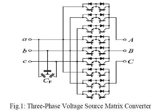 |
| To produce an active voltage to the load, one of three-phase input voltages can be selectively connected to each output terminal. To produce a zero voltage, all the load terminals have to be connected to one of the input source terminals. Note that no shoot-through switching states are allowed to the input source side, and no open circuits allowed to the output side. Again, like the VS inverter, the VS-MC features inherent buck operation with the maximum voltage ratio of 0.866 [1]. |
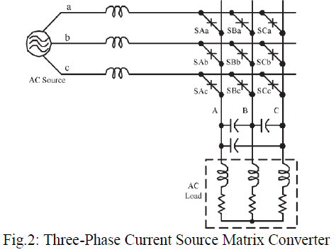
| The current-source matrix converter (CS-MC) in Fig. 2 [33] can be seen as the dual circuit of the VS-MC. The CS-MC is fed from a current source, and the load has to be capacitive. |
| The CS-MC cannot have open-circuit to the input side and short-circuit to the output side. Its output voltage is always greater than the input voltage. A buck-boost matrix converter can be implemented through a combination of the VS-MC and CS-MC. So, buck-boost matrix converters require two stages and 18 ac switches, which results in high cost, complex control strategy, low efficiency, and low reliability. In addition a proper commutation method has to be employed for safe switching to avoid an open-circuit or short-circuit in both converters. |
 |
| With latest development of Z-source inverter with inherent simultaneous buck-boost capability [24], many contributors have extended this concept to other topologies as well [25]–[29]. However, the frequency is not changed in their Z-source AC/AC converters [27], [28]. This paper reviews a family of Z-source matrix converters (ZS-MCs) along with other earlier topologies of matrix converter. |
MC TOPOLOGICAL DEVELOPMENT |
A. Basic Matrix Converter Topologies |
| Forced commutated ac-ac converter topologies that can provide simultaneous amplitude and frequency transformation of multi-phase voltage-current systems without intermediate energy storage are referred to as Matrix Converters (MCs) [34]. MCs can generate sinusoidal input currents and output voltages with higher electrical output frequencies than the input frequency. |
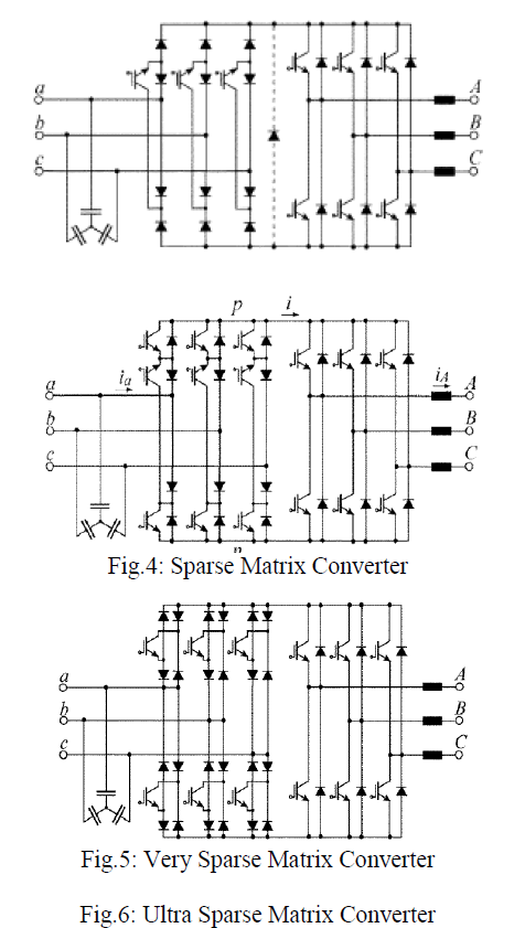
| The three-phase to three-phase Half-Bridge MC topology, nowadays usually referred to as direct or Conventional Matrix Converter (CMC) (Fig. 1) [34] performs the voltage and current conversion in one semiconductor stage by using an array of nine controlled bidirectional switches. Alternatively, the Indirect Matrix Converter as shown in Fig. 3[35] features a two-stage (indirect) power conversion with a bidirectional, unipolar current source input stage with six bidirectional switches and a two-level voltage source converter output stage. |
| With the help of research done by Venturini and Alesina in l980 the actual development of the modern highfrequency modulated CMC topology started [34]. They described the power circuit of the CMC as a matrix of bidirectional switches and introduced the name “Matrix Converter”. In order to prove the MC concept for practical converter systems, numerous application specific research projects have been conducted, starting with the investigation of ac motor drives supplied by CMCs. Neft and Schauder in 1988 [37] has done successful experiment of using CMC for vector control of an induction machine. First publications describing the IMC topology was done in 1989 by Holtz and Boelkens [38]. First experimental results of IMCs were presented such as by Zwimpfer and Stemmler in 2001[40]. |
 |
| In 1986 Ziogas suggested an indirect MC topology, which is equivalent to a Voltage Source Back-to-Back Converter (V-BBC) without a dc link capacitor[41] and Kim et al analyzed the same in much detail in 1998[42].This converter topology cannot provide sinusoidal input currents and was named as the Fundamental Frequency Front- End Converter by Gopfrich and Rebereh in 2003 [43] .A sinusoidal shape of the input currents can be obtained by implementation of a separate input stage for each input phase as proposed in 1998 by Mino et al in [44]. |
| Jones and Bose provided the basis for the three-phase to single-phase MC topology with their investigation of the three-phase to single-phase FCCC in 1986. Khan et al proposed in 1986 a single-phase to three-phase topology [45].In 1997; Zuckerberger demonstrated the operating behavior of a single-phase to single-phase MC [46]. |
| To reduce number of switches major step was taken with regard to the further development of MC topologies occurred in 2001 as IMC topologies known as Sparse Matrix Converters as shown in Fig. 4[36] by Kolar et al’followed by the first experimental results of a Very Sparse Matrix Converter [36] (Fig. 5). Ziegler et al in 2004 proposed possible circuit topologies referred as as S-A-X converters. The same concept was proposed in 2002 by Kolar et alfor the Sparse Matrix Converters known as Ultra Sparse Matrix Converter as shown in [36] (Fig. 6). |
 |
B. Z Source Matrix Converter Topologies |
| Both the V-source Matrix converter and the I-source Matrix converter have the following common problems. |
| 1) They are either a boost or a buck converter and cannot be a buck–boost converter. That is, their obtainable output voltage range is limited to either greater or smaller than the input voltage. |
| 2) Their main circuits cannot be interchangeable. In other words, neither the V-source converter main circuit can be used for the I-source converter, nor vice versa. |
| 3) They are vulnerable to EMI noise in terms of reliability. |
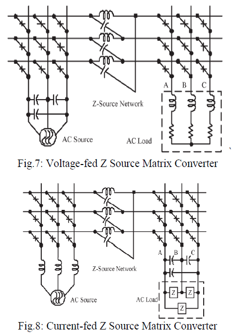
| To overcome the above problems of the traditional V-source and I-source converters, an impedance-source (or impedance-fed) power converter (known as Z-source converter) and its control method for implementing dc-to-ac, ac-to-dc, ac-to-ac, and dc-to-dc power conversion has been recently proposed by Ge and Peng [33]. Fig. 7 and Fig. 8 shows the ZS-MCs, which consist of three parts: source-side MC, Z-source network, and load-side MC. Like the Z-source inverters, the ZS-MCs can be voltage-fed and current-fed types. Fig. 7 shows the voltage-fed ZS-MC and Fig. 8 for the current-fed ZS-MC [33]. The main feature of the ZS-MCs is to fulfill both buck and boost operation. That is, they can step down and up the source voltage. |
 |
| Fig. 9 shows a simplified voltage-fed ZS-MC, where the source-side MC in Fig. 7 is replaced by a three-phase ac switch S0. The simplified voltage-fed ZS-MC is operated in the same manner as the traditional VS-MC in Fig. 1 when the three-phase switch S0 is kept on, |
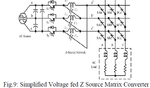 |
| to produce active voltages and zero voltage to the load, which is the buck mode. The shoot-through state is inserted in the PWM pulses of MC when the voltage boost is needed. The three-phase switches are turned off during shoot-through states to avoid short circuit at input side. The voltage is boosted with no introduction of distortion to the original intended output voltage waveform by shooting-through the MC during the zero-voltage switching states. The greater the output voltage can be obtained by longer shoot-through intervals. Also, it has lesser switch count, compared with the combination shown in Fig. 7[33]. Fig. 10 [33] shows a simplified currentfed ZS-MC, in which the source-side MC is replaced by a three phase switch. |
 |
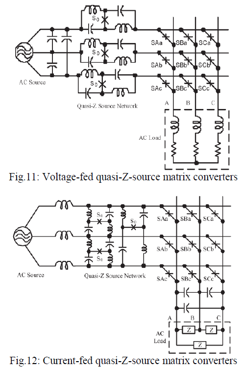
| Fig. 11[33] and Fig 12[33] show the voltage-fed and current-fed quasi-Z-source matrix converters (qZS-MCs), like qZS inverters [25]. Their operations are similar to that of the simplified ZS-MCs. Good features about the qZS-MCs are that the infinite voltage gain can be achieved and that the Z-source networks are minimized in terms of voltage and current ratings. |
 |
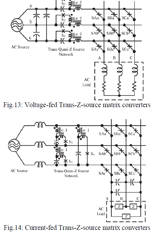
| Fig. 13[33] and Fig. 14 [33] shows two trans-ZS matrix converters. As trans-ZS inverters [29], the trans-ZS converters can have higher voltage boost while reducing voltage stress. The trans-ZS matrix converters can be controlled in an exactly the same manner as the simplified ZS-MCs. They are suited for the applications where high voltage boost is required. |
 |
POWER SEMICONDUCTOR DEVICES |
A. Bidirectional Switches |
| The possibilities to implement the bidirectional switch with IGBTs are presented in Fig. 15[34]. The configuration in Fig. 15(a) contains only one active switch and is the simplest choice. However, it cannot be used in MCs with most safe commutation methods. In addition, it has more conducting components in a supply-to-load current path than the configurations in Fig. 15 (b–f). However, it could be used with some two-stage MC topologies and it was applied with MOSFET in one of the first experimental verifications of MC drives in 1988 [47]. |
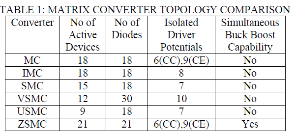
| The most popular MC switches have been common-emitter and common-collector configurations (Fig. 15 b–c) and their combinations [1]. They both always have a single active switch and a single diode conducting per output phase. The only difference is the number of required isolated emitter potentials. A common-collector switchbased DMC requires six isolated gate control units, whereas the common-emitter-based DMC, shown in Fig. 15 (b), requires nine isolated gate control units. So common-collector switch-based DMC is preferred. |
| The separated series combinations (Fig. 15 d–e) are not as commonly used as the previous two and they have similarities with the switches required in the current source converter (CSC). However, differences arise with the number of isolated gate drivers: with the DMC, the configuration in Fig. 15(d) requires eighteen isolated gate drivers, whereas the configuration in Fig. 15(e) requires only six, as in the common-collector configuration. |
| The similarity between the MCs and the CSCs continues with the benefits provided by the RBIGBTs Fig. 15(f) [48].There is only a single RBIGBT conducting per output phase. However, they are still quite new and their switching characteristic is not necessarily comparable to that of conventional IGBTs yet . Most experimental results for a full DMC system with eighteen RBIGBTs are presented with voltage levels lower than 400 V, e.g. in [49], [50]. In addition, there seem to be differences which depend on the manufacturer whose RBIGBT is applied in each case. |
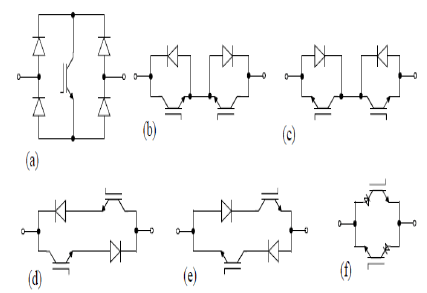 |
| Fig. 15: Bidirectional switch configurations in practice: (a) switch and Diode Bridge, (b) common- emitter, (c) common-collector, (d) diode and switch in series, (e) diode and switch in series and (f) anti parallel RBIGBT configuration. |
B. Integrated Power Modules |
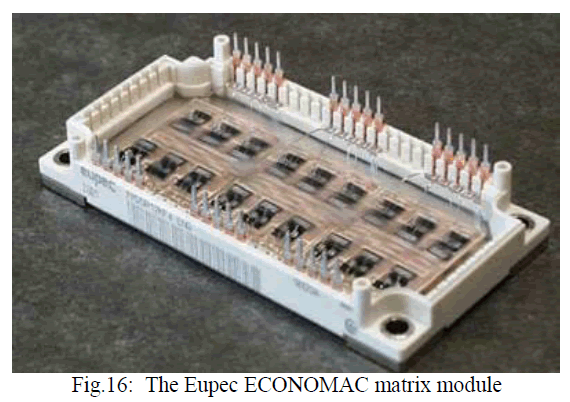
| It is possible to construct the common emitter bidirectional switch cell from discrete components, but it is also possible to build a complete matrix converter in the package style used for standard six-pack IGBT modules. This technology can be used to develop a full matrix converter power circuit in a single package. This has been done by Eupec using devices connected in the common collector configuration as shown in Fig. 16 [51] and is now available commercially. |
 |
Different Matrix Converter Topologies Comparison |
 |
CONCLUSION |
| Matrix converter has been frequently presented as future converter for AC drive application. Matrix converter circuits offer the following effects comparing to conventional AC Drive circuits. 1. Suppression of power harmonics: Realizes less than 7% THD of input current and more than 98% input power factor without any specific measures taken. 2. Longer operating life: The main circuit does not have endurable parts such as an electrolytic capacitor. This makes the operating life of the main circuit longer and the maintenance interval longer. 3. Elimination of derating: With the elimination of current constriction on any specific device, the reduced operation during low-frequency operation is unnecessary. 4. Power regeneration: Unique bi-directional switches for directly connecting the power supply and loads enable continuous regeneration. 5. High-efficiency: Only the bi-directional switches are used to connect the power supply and loads, allowing higher-efficient operation than as in conventional AC Drives. However despite intensive research for the last thirty years, matrix converter has achieved low market penetration. The reason for the same till now is the low input to output voltage transfer ration of 86%. But a major future task of research is seen to use recently proposed Z source converter topology to improve the voltage transfer ratio of matrix converter. |
References |
|