ISSN ONLINE(2278-8875) PRINT (2320-3765)
ISSN ONLINE(2278-8875) PRINT (2320-3765)
D.Kousalya1, N. Manoj Kumar2
|
| Related article at Pubmed, Scholar Google |
Visit for more related articles at International Journal of Advanced Research in Electrical, Electronics and Instrumentation Engineering
Direct Torque Control (DTC) is one of the excellent control strategies of torque and flux control in induction machine. The hysteresis comparators are used to compensate the error between estimated and reference torque and flux. The major problems aroused in DTC drives are steady state torque and flux pulsations. This paper presents a new strategy to direct torque control of induction motor drive based on new space vector modulation. It can reduce steady state torque, flux, current, and speed pulsations. In the proposed approach, the error between the estimated and reference torque and flux will be compensated by generated space voltage vector. Complexity in time duration is minimised by measuring sector local angle. The performance of the proposed control method is simulated using MATLAB/SIMULINK. It is concluded that the proposed method produces less torque and flux ripple in steadystate operation than the classical DTC
Keywords |
| Direct Torque Control, Space Vector Modulation, Induction Motor. |
INTRODUCTION |
| In nineties, direct torque control of induction machines has been developed. It gives fast and good dynamic torque response. DTC can be considered as substitute to the field-oriented control (FOC) technique [1], [2]. The DTC scheme as initially proposed is very simple which consists of a pair of hysteresis comparators, torque and flux calculator, a lookup table, and a voltage-source inverter (VSI). The main advantages are it does not require any transformation or PWM pulse generation and current regulators. It minimizes the use of machine parameters [3], which results in less sensitive to parameter variations. The main drawbacks of DTC are variations of the switching frequency of inverter and torque ripple [4]. The root cause to the variable switching frequency problem is the use of hysteresis comparators. An analysis of the switching frequency for hysteresis-based controllers in DTC drives is presented in [5]. It is shown that the switching frequency is highly influenced by the motor speed, which is mainly due to the torque slope that depends on motor speed. The problem of variable switching frequency can be solved by two methods: first method is using variable hysteresis bands to maintain a constant switching frequency [6], but it’s implementation will increase the complexity and second method is performing the switching at regular intervals [7] [8], But In case an active or zero voltage vector is applied for the whole switching period, then the torque ripple will inevitably become high. Several techniques have been developed to diminish torque ripple. The pulse duration of the output voltage vector is determined by the torque ripple minimum condition [9]. This method can significantly decrease the torque ripple, but they increase the complexity of the DTC algorithm. |
| This paper proposes simple and effective control strategy to maintain constant switching frequency and to minimize the torque ripple in DTC. To maintain a constant switching frequency, a simple PI torque and flux controller is introduced to replace the hysteresis comparator. The proper voltage vector is selected using new space vector modulation technique. Thus, the torque ripple is smaller compared to the hysteresis band controller. The simulation results shows that torque, flux ripple are decreased and constant switching frequency is maintained with proposed technique. The section II describes the mathematical modelling of induction motor. Direct Torque Control with modified SVM scheme is described in section III. Simulation results and conclusions are presented in section IV and section V respectively. |
INDUCTION MACHINE MODELLING |
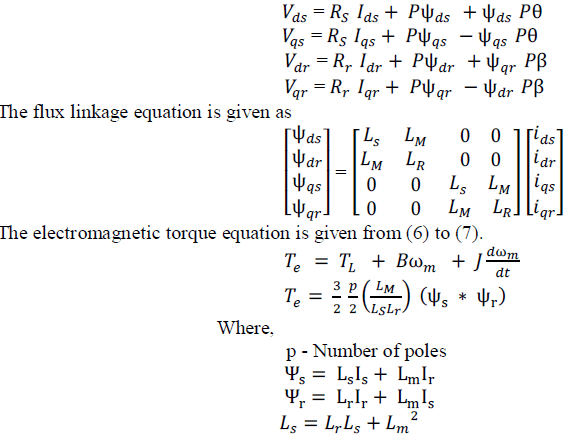
| The voltage balance equations for the d-q coils are represented in terms of space voltage vector in a stationary reference frame as given in equation (1) to (4). |
 |
 |
DIRECT TORQUE CONTROL WITH MODIFIED WITH SVM SCHEME |
| The principle behind direct torque control of induction motor drive is to control the flux linkage and electromagnetic torque directly by the selecting proper inverter switching state with the help of lookup table. The conventional DTC includes two level and three level hysteresis controllers, three level for torque and two level for flux linkage. Even though it has many advantages like no feedback control, no traditional PWM algorithm, no vector transformation, it has some drawbacks like variable switching frequency, inherent steady state torque and flux ripple. Due to hysteresis band controller, steady state torque and flux ripple is more in direct torque control of induction motor which is undesirable from smooth response point of view. Direct Flux and Torque Control with Space Vector Modulation (DTC-SVM) schemes are proposed in order to overcome the drawbacks of the classical DTC of Induction motor. The DTC-SVM strategy operates at a constant switching frequency is shown in Fig.1. |
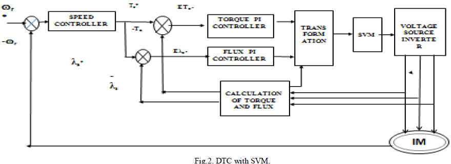 |
| The inverter is controlled by the space vector modulation technique instead of voltage sector selection block as used in classical DTC. The controllers calculate the required stator voltage vector and then it is realized by space vector modulation technique. In this scheme there are two proportional integral (PI) type controllers instead of hysteresis band to regulate the torque and the magnitude of flux. By controlling torque and flux amplitude, a gate signal for inverter is generated. Space Vector Modulation (SVM) Technique has become the most popular and important PWM technique for the control of AC motors. Space vector modulation is a digital technique which is used to create a reference voltage vector by modulating the switching time of space vectors in each of the six sectors shown in Fig. 3. |
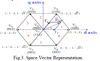 |
| In space vector modulation technique , the inverter can be treat as a single unit, instead of three separate push pull drives as in sine PWM. This PWM technique approximates the reference voltage Vref by a combination of the eight switching patterns (V0 to V7) [10]. The concept of space vectors is derived from the rotating field of AC machine which is used for modulating the inverter output voltage. Space vector PWM can be implemented by the following steps: |
| 1) Calculation of Vd,Vq,Vref, α. |
| 2) Calculation of local theta. |
| 3) Calculation of time duration. |
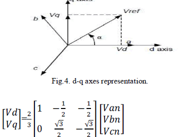
1) Calculation of Vd,Vq,Vref,α: Two phase (d-q) representation of three phase voltage is shown in Fig4. |
 |
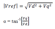 |
| 2) Calculation of local theta (): The angle α is measured with respect to d-axis component of voltage. To use common time duration formula for all sectors active and non-active vectors duration, it is necessary to find out local theta for each sector using following equation. |
 |
| 3) Calculation of time duration: The principle of SVPWM method is that the command voltage vector is approximately calculated by using three adjacent vectors. The duration of each voltage vectors obtained by using voltage time equation of vector calculation: |
 |
 |
| In space vector PWM technique, the required space vector is synthesizes by two adjacent vector and null vector. Switching time duration at sector one, can be calculated. |
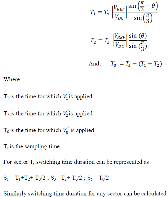 |
SMULATION RESULTS |
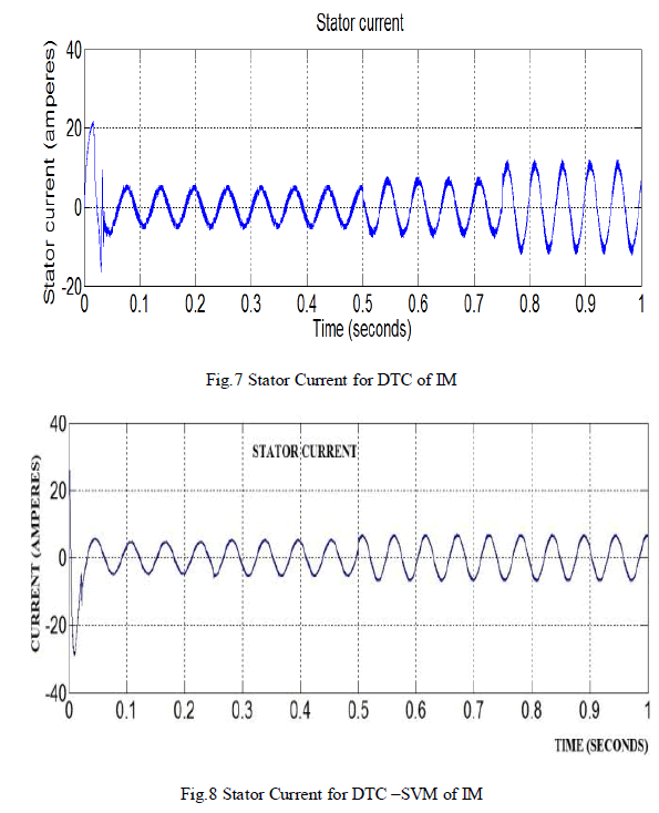
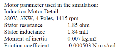
| To validate the effectiveness of the SVM based DTC methods, a two-level SVM based DTC motor drive was developed and simulation results are presented here. The space vector modulation based DTC drive is illustrated in Fig. 2. Space vector modulation technique is employed in closed loop torque and flux control to generate inverter switching states. A simulation work has been carried out on induction motor with the specifications given in appendix. The proposed scheme is simulated in MATLAB/SIMULINK. The Fig. 7 and Fig. 8 shows stator current for DTC of induction motor and SVM based DTC of induction motor. In classical DTC and SVM based DTC a steady state load torque of 5Nm is applied at time t = 0.5s. Current is increased from 5A to 7A. But current in DTC with SVM has less pulsation. |
 |
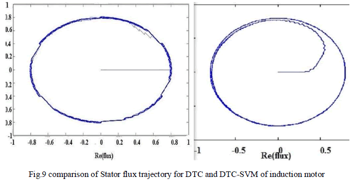
| Stator flux of direct torque control and SVM based direct torque control of induction motor is shown in Fig.9 .When compare with DTC and SVM based DTC, stator flux is more uniform in DTC with SVM. Electromagnetic torque response for DTC and SVM based DTC for induction motor is shown in fig.10 and fig. 11. |
 |
| The Fig. 10 shows the electromagnetic torque for DTC of induction motor. Initially the motor oscillates with a maximum torque of 30 Nm and settles at 0 Nm for 0.035seconds. When half of load torque of 10 Nm is applied at 0.5 seconds applied, motor initially oscillates and then settles at steady. In steady state the load torque oscillates between maximum and minimum value of 13 Nm to 7Nm at t = 0.6s. |
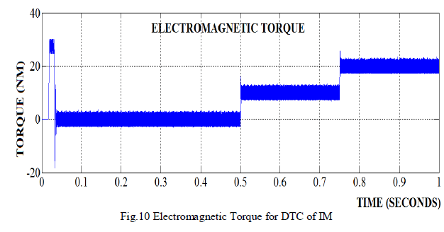 |
| When full load torque of 20 Nm is applied, output torque rises and oscillates between maximum and minimum torque of 23 Nm and 17 Nm respectively.When half of load torque s applied, rotor speed decreases slightly below 500 RPM momentarily and remain constant for remaining periods in both DTC and DTC-SVM of induction motor. |
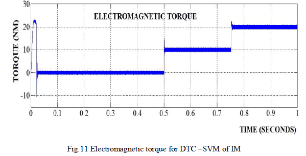 |
| In SVM based direct torque control when motor is starts with zero load torque at t=0s, it will oscillates up to 25Nm and settles to its steady state at t = 0.028s in direct torque control. |
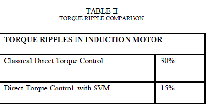 |
| When half of load torque of 10 Nm is applied at 0.5 seconds applied, motor initially oscillates and then settles at steady. In steady state the load torque oscillates between maximum and minimum value of 11 Nm to 9.2Nm at t = 0.6s. When full load torque of 20 Nm is applied, output torque rises and oscillates between maximum and minimum torque of 20.8 Nm and 19.1 Nm respectively. Comparison of torque ripple in DTC and DTC with SVM is shown in table. Therefore from results in table it is inferred that proposed scheme has less torque ripple. |
CONCLUSION AND FUTURE WORK |
| In this paper, new direct torque control strategy based on PI controllers and new space vector modulation technology for induction machines has been proposed. Implementation of space vector modulation is achieved using local theta which reduces time duration calculation complexity. DTC with SVM achieves constant switching frequency and reduced torque ripple. Multilevel inverter has less total harmonic distortion when compared with two-level inverter and fuzzy is one of well soft computing technique which will minimize torque and flux error very accurately than PI control which will scope for future. The simulations results verify that the proposed SVM based DTC improves the torque control. |
APPENDIX |
 |
References |
|