ISSN ONLINE(2278-8875) PRINT (2320-3765)
ISSN ONLINE(2278-8875) PRINT (2320-3765)
N.VijayaSarathi1, C.Mohanapriya2
|
| Related article at Pubmed, Scholar Google |
Visit for more related articles at International Journal of Advanced Research in Electrical, Electronics and Instrumentation Engineering
Two mode strong changes use the half bridge inverter in two operating modes to achieve efficiency in a wide power levels. By comparing with dual mode resonant converter the class D full bridge resonant inverter operates only in single mode where low range of power levels are not possible. The dual mode strong change can operate with Zero Voltage Switching and Zero Current Switching so the switching losses are minimised. Induction heating is the fast growing technology in domestic appliances it has high efficiency and faster heating times. In this paper dual mode deep change function has been used for heating system applications.
Keywords |
| Induction heating (IH), Half bridge inverter, resonant converter. |
INTRODUCTION |
| The main advantage of domestic induction heating is cleanliness, rapid heating, high power densities, accurate time and temperature control. IH is a non contact process. It uses high frequency electricity to heat materials that are electrically conductive. When the pot is directly heated by the induced currents generated within a varying magnetic field in the range of 20-100KHZ.The magnetic field is generated by a inductor coil system, supplied by a resonant converter. In Resonant converter higher output occurs at resonant frequency, yielding efficiency also high. The conventional series half bridge ZVS resonant inverter is using IH application. |
| In this converter the resonance frequency is higher than the switching frequency, yielding to the maximum efficiency at maximum output. Whereas if the switching frequency is higher than the resonant frequency. Thus with the increased switching frequency the losses are increased for lower power output range [2] [3].To overcome this limitation dual mode resonant converter is used. The main advantage of resonant converter is to improve the efficiency even at low output power range by reducing switching losses. Class-D half-bridge converter is used in the high output power range, whereas class-DE half-bridge converter [3], [4] is used in the low to medium output power range. The combination of these operation modes achieves high efficiency levels in a wider range of output power levels. |
HALF BRIDGE RESONANT CONVERTER |
| The conventional method used half bridge series resonant converter. It is one switch topology method for medium-high output power levels due to its high efficiency and low voltage stress across the switching devices. In Half bridge resonant converter consist of passive resistance and inductance. The series resonant half bridge applied to induction heating operates at switching frequency higher than the resonant frequency to achieve soft switching conditions. To reduce switching losses a snubber capacitor is added. |
| In class D operation mode implies the snubber capacitor Cs is much lower than the resonant capacitor Cr .In class-DE operation mode is achieved at ZVS and Zero Voltage derivative Switching (ZVDS) at the turn off. The change of mode from class D to class DE occurs by changing the capacitor values. |
TWO MODE DEEP CHANGER |
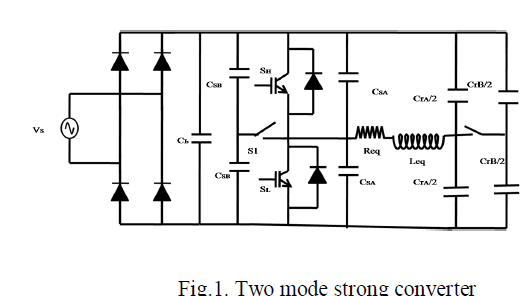 |
| The dual mode resonant converter can be used in order to improve efficiency in whole operating range. In dual mode resonant converter electromechanical switches SPST 1 and SPST 2 allow varying the snubber and resonant capacitance in order to change the operation mode. They are six operation modes for the converter. |
MODE I: |
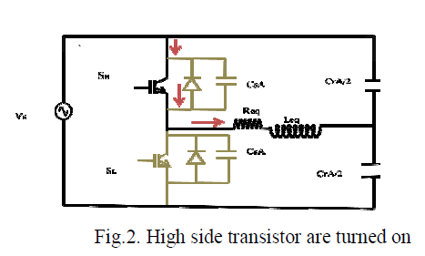 |
| In mode I when high side transistor is turned on low side transistor are turned off the load current is positive and it flows to the load. |
MODE II: |
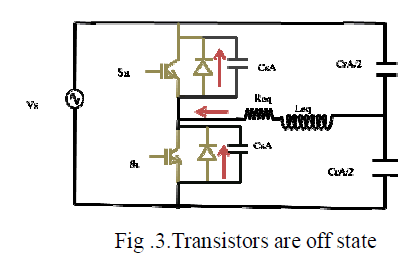 |
| When high-side transistor is turned off. The switch-off current is used to charge/discharge the snubber capacitors. The high-side snubber capacitor is charged to the supply voltage. The low -side snubber capacitor is discharged there is no power flows to the load. |
MODE III: |
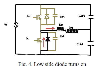 |
| Both the side high and low side transistor are turned off.The load current is positive. It is supplied by the low-side diode. The power flows to the load. |
MODE IV: |
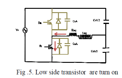 |
| When low side transistor are turned on.The load current becomes negative no power flows to the load. |
MODE V: |
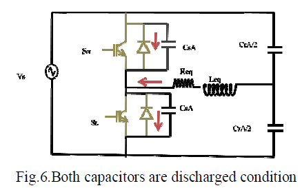 |
| The low-side transistor is deactivated. The load current charges the low-side snubber capacitor to the supply voltage. The high-side snubber capacitor is discharged. |
MODE VI: |
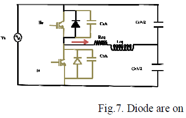 |
| When both snubber capacitors are charged/discharged. The negative load current flows through the high-side diode. |
SIMULATION |
| The simulation is done in a step by step manner in MATLAB-Simulink R2010a.The simulation of entire Series Resonant Converter system with diode bridge rectifier, inductor, capacitor. |
SIMULATION CIRCUIT IN D MODE: |
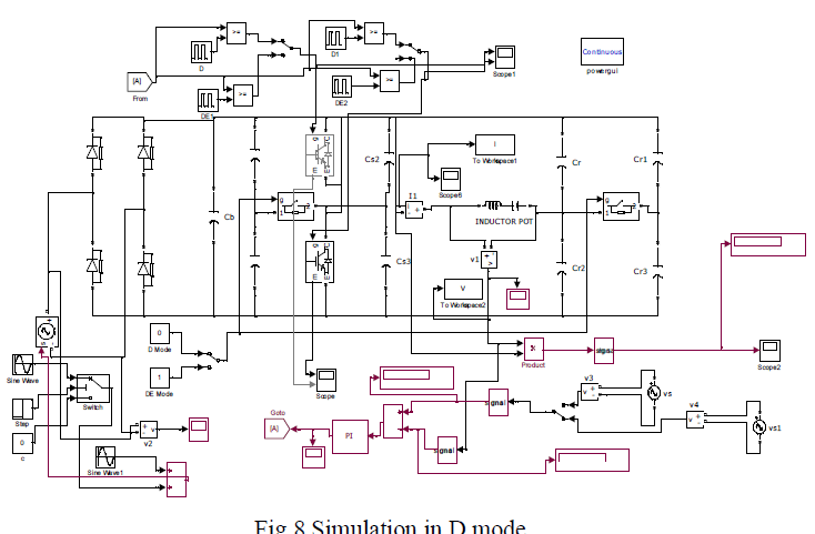 |
| The results for the simulation of class D under varying Power, voltage and current are shown below |
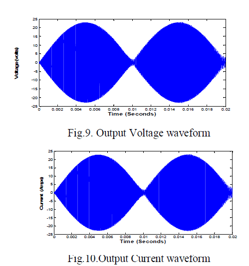 |
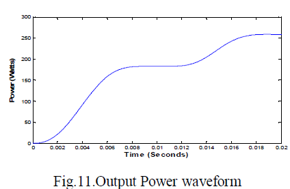 |
SIMULATION CIRCUIT IN DE MODE |
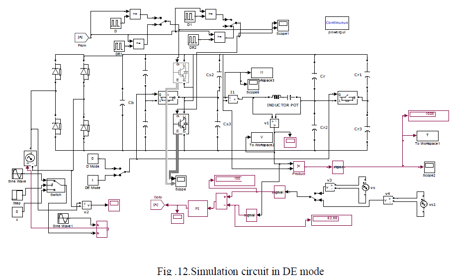 |
| The results for the simulation of class DE under varying Power, voltage and current are shown below |
Output waveforms in DE mode |
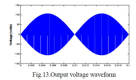 |
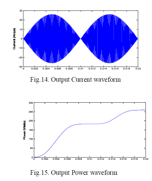 |
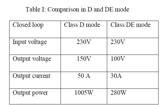
| In Fig 10 and 15we get the Output Power, Voltage, Current .Comparison between D and DE mode are listed below. |
 |
CONCLUSION |
| Class-D half bridge converter is used in the high output power range, whereas class-DE half-bridge converter is used in the low to medium output power range. The combination of these operation modes achieves high efficiency levels in a wider range of output power levels. In the dual-mode resonant converter, class -D and class- DE operation modes are combined to optimize the efficiency in wide range of output power levels. Thus, the presented dual-mode resonant converter topology is a cost-effective implementation for domestic induction heating appliances. |
References |
|