International Journal of Advanced Research in Electrical, Electronics and Instrumentation Engineering
ISSN ONLINE(2278-8875) PRINT (2320-3765)
ISSN ONLINE(2278-8875) PRINT (2320-3765)
V.Arun1, N.Prabaharan1, K.Raja1, B. Shanthi2
|
| Related article at Pubmed, Scholar Google |
Visit for more related articles at International Journal of Advanced Research in Electrical, Electronics and Instrumentation Engineering
This paper presents a new structure of multilevel inverter. Multilevel inverter is triggered by using Unipolar Pulse Width Modulating (UPWM) strategies using Trapezoidal Amalgamated Rectangular (TAR) reference with triangular carriers. The performance measures like Crest Factor (CF), Distortion Factor (DF), Form Factor (FF), VRMS (fundamental) and Total Harmonic Distortion (THD) are evaluated for various PWM strategy and different modulation indices. Simulation is performed by using MATLAB-SIMULINK
Keywords |
| APOD, CO, PD, UPWM, VF, TAR. |
INTRODUCTION |
| Multilevel inverters have become an effective and practical solution for increasing power and reducing harmonics of AC waveforms. By synthesizing the AC output voltage from several levels of DC voltages, staircase output waveform can be produced. This allows for higher output voltage and simultaneously lowers the stress on the semiconductor device. Among the various topologies, asymmetric cascaded MLI is employed as it requires three unequal dc sources for producing a 15-level output. Bodo et al [1] analyzed carrier-based PWM techniques for a five-phase open-end winding drive topology. Dordevic et al [2] made a comparison of carrier-based and space vector PWM techniques for three-level five-phase voltage source inverters. Kostic et al [3] introduced a new approach to theoretical analysis of harmonic content of PWM waveforms of single and multiple-frequency modulators. Batschauer et al [4] analyzed three phase hybrid multilevel inverter based on half bridge modules. Porselvi and Muthu [5] made a comparison of cascaded H-bridge, neutral point clamped and flying capacitor multilevel inverters using multicarrier PWM. Nami et al [6] analyzed voltage-sharing converter to supply single-phase asymmetrical four-level diode-clamped inverter with high power factor loads. Bensraj et al [7] developed unipolar pwm using trapezoidal amalgamated rectangular reference function for improved performance of multilevel inverter. Farid et al [8] developed new techniques of controlled PWM inverters. Govindaraju and Baskaran [9] proposed hybrid phase disposition PWM control method for multilevel inverter survey on cascaded multilevel inverters. This paper focuses on a single phase asymmetric DC source 15 level inverter topology by using UPWM switching strategies. Simulations were performed by using MATLAB-SIMULINK. Harmonic analysis and evaluation of different performance measures for various modulation indices have been carried out and presented. |
II. PROPOSED ASYMMETRICAL MULTILEVEL INVERTER |
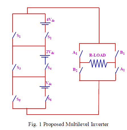
| The proposed new asymmetric cascaded multilevel inverter is shown in Figure 1. Proposed inverter consists of 3 sub multilevel inverter and H-bridge module. Conversion cell consists of separate voltage sources (Vdc, 2Vdc, and 4Vdc) connected in cascade and two active switching elements that can make the output voltage in positive polarity with several levels. H-bridge consists of four active switching elements that can make the output voltage in positive or in negative polarity depending on the switching condition. By using Vdc, 2Vdc and 4Vdc, it can synthesize 15 output levels: -7Vdc, -6Vdc, -5Vdc, -4Vdc, -3Vdc, -2Vdc, -Vdc, 0, Vdc, 2Vdc, 3Vdc, 4Vdc, 5Vdc, 6Vdc, 7Vdc. Expected output voltage level is given by |
| Vn=2n+1-1, where n=1, 2, 4……. |
 |
III.TAR BASED PWM STRATEGIES |
| In this proposed work a Unipolar TAR reference with a triangular carrier is used to generate firing pulses for a 15 level inverter. The carrier signals are concerned, there are multiple Control Freedom Degree (CFD) including frequency, amplitude, phase of each carrier and offsets between carriers. The modulating/ reference wave of multilevel carrier based PWM strategies can be sinusoidal or trapezoidal. As far as the particular reference wave is concerned, there is also multiple CFD including frequency, amplitude, phase angle of the reference wave and as in three phase circuits, the injected zero sequence signal to the reference wave (7). For an m-level inverter using Unipolar strategies, (m-1)/2 carriers with the same frequency fc and same peak-to-peak amplitude Ac are used. The reference waveform has amplitude Am and frequency fm and it is placed at the zero reference. The reference wave is continuously compared with each of the carrier signals. If the reference wave is more than a carrier signal, then the active devices corresponding to that carrier are switched on. Otherwise, the device switches off. There are many alternative strategies are possible, some of them are tried in this paper and they are: |
| a. Unipolar Phase disposition PWM strategy (UPDPWM) |
| b. Unipolar Alternate phase opposition disposition PWM strategy (UAPODPWM) |
| c. Unipolar Carrier overlapping PWM strategy (UCOPWM) |
| d. Unipolar Variable frequency PWM strategy (UVFPWM) |
| The formulae to find the Amplitude of modulation indices are as follows: |
| For UPDPWM, UAPODPWM and UVFPWM |
| ma= 2Am /( m-1)Ac ) |
| For UCOPWM |
| ma =Am /(2*Ac) |
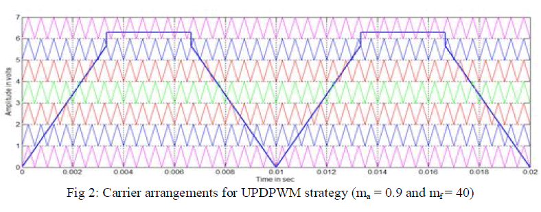
A. Unipolar Phase disposition PWM strategy (UPDPWM) |
| In case of UPDPWM strategy, all the carrier waveforms are each in phase. The carrier arrangement of TAR reference is illustrated in figures 2. |
 |
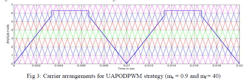
B. Unipolar Alternate phase opposition disposition PWM strategy (UAPODPWM) |
| In UAPOD strategy the carriers of same amplitude are phase displaced from each other by 180 degrees alternately. The carrier arrangement of TAR reference is illustrated in figures 3. |
 |
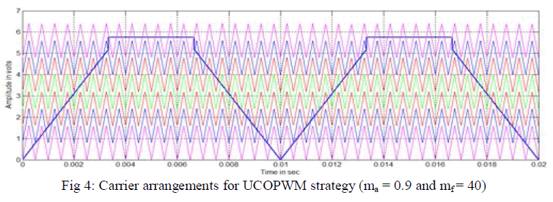
C. Unipolar Carrier overlapping PWM strategy (UCOPWM) |
| In UCOPWM strategy, carriers with the same frequency fc and same peak-to-peak amplitude Ac are disposed such that the bands they occupy are overlapping each other; the overlapping vertical distance between each carrier is Ac/2. The carrier arrangements of TAR reference are illustrated in figures 4. |
 |
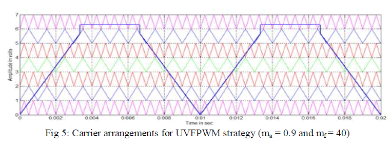
D. Unipolar Variable frequency PWM strategy (UVFPWM) |
| The number of switching’s for upper and lower devices of chosen MLI is much more than that of intermediate switches in PWM using constant frequency carriers. In order to equalize the number of switching’s for all the switches, variable frequency PWM strategy is used as illustrated in Fig.5 in which the carrier frequency of the intermediate switches is properly increased to balance the number of switching’s for all the switches. |
 |
IV. RESULT AND DISCUSSION |
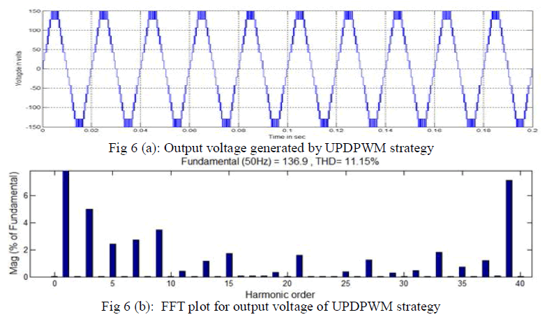
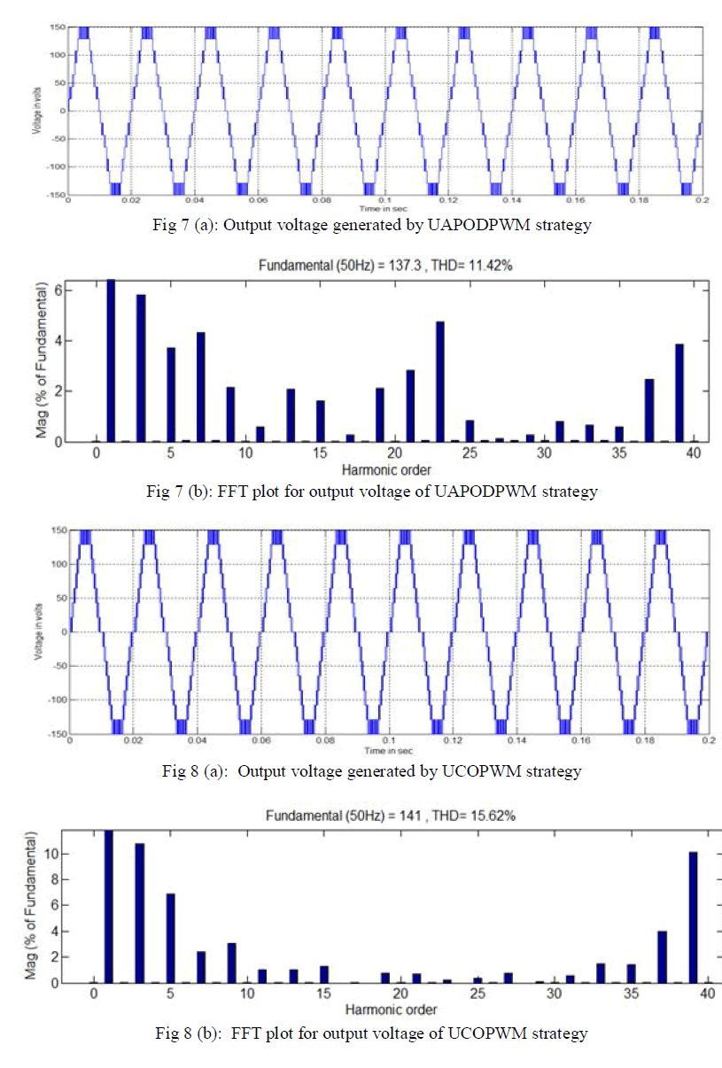
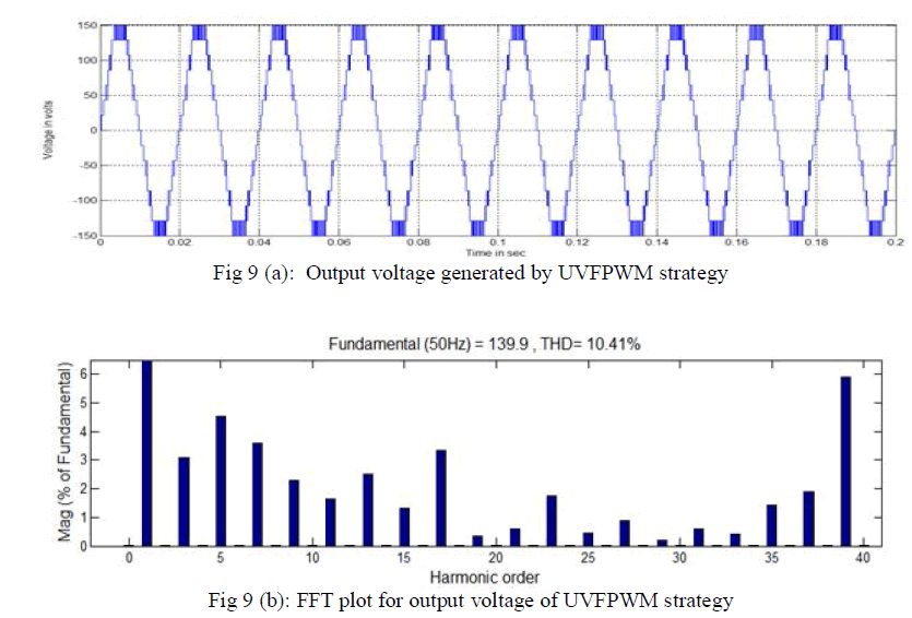
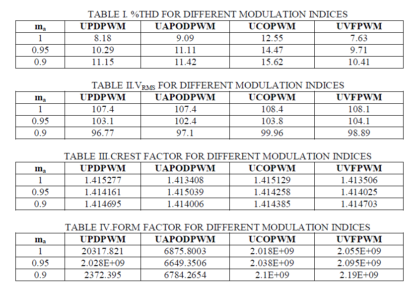
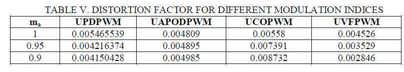
| The single phase binary DC source 15 level inverter is modeled in SIMULINK using power system block set. Switching signals for binary multilevel inverter using UPWM strategies are simulated. Fig.6 (a) and (b) respectively shows the 15 level output voltage generated by UPDPWM strategies and its FFT plot. Fig.7 (a) and (b) respectively shows the 15 level output voltage generated by UAPODPWM strategies and its FFT plot. Fig.8 (a) and (b) respectively shows the 15 level output voltage generated by UCOPWM strategies and its FFT plot. Fig.9 (a) and (b) respectively shows the 15 level output voltage generated by UVFPWM strategies and its FFT plot. Simulations were performed for different values of ma ranging from 0.8 to 1 and the corresponding %THD is measured using the FFT block and their values are shown in Table I. In that UVFPWM strategy provides low %THD. Table II represents the VRMS of the inverter output voltage. In that UCOPWM strategy provides higher fundamental RMS voltage. Table III represents the crest factor of the output voltage. Table IV and V represents the form factor and distortion factor of the output voltage. In that UVFPWM strategy provides low DF. FF and CF should be same for all modulation indices. For ma= 0.9, it is observed from the figures [6b 7b 8b 9b] the harmonic energy is dominant in: 6b) 3rd, 9th, 39th order in UPDPWM strategy. 7b) 3rd, 5th, 7th, 23rd, 39th order in UAPODPWM strategy. 8b) 3rd, 5th, 39th, order in UCOPWM strategy. 9b) 3rd, 5th, 7th, 17th, 39th order in UVFPWM strategy. The following parameter values are used for simulation: Vdc =21.5V, R (load) = 100 ohms, fc=2000 Hz and fm=50Hz. |
 |
 |
 |
 |
 |
V.CONCLUSION |
| In this paper, UPWM strategy for asymmetric DC source 15 level inverter has been presented. Binary DC source multilevel inverter gives higher output voltage with reduced switch count and low harmonics. Performance factors like % THD, VRMS, CF, FF and DF have been evaluated presented and analyzed. It is found that the UVFPWM strategy provides relatively lower %THD, UCOPWM strategy is found to perform relatively higher fundamental RMS output voltage. CF is almost same for all the strategies. FF is almost same for all the strategies. DF relatively low in UVFPWM strategy. |
References |
|