ISSN ONLINE(2278-8875) PRINT (2320-3765)
ISSN ONLINE(2278-8875) PRINT (2320-3765)
Laxmi Nidhi1, Pratyusha Roy2, Srishty Nayak3 , Rajine swetha R4
|
| Related article at Pubmed, Scholar Google |
Visit for more related articles at International Journal of Advanced Research in Electrical, Electronics and Instrumentation Engineering
From ages it has been a desire of humans to achieve the ultimate in security and make his loved ones and loved things secure. It is this desire that prompted him to make the boundaries and secure them too from all unseen and unknown sources. For this it has been always necessary to maintain a huge sum of people to guard and raise alarms in cases of emergencies. To accomplish this we propose a mechanism which will employ image processing in which a camera (webcam) will be continuously observing the „area under surveillance‟. This data will be then processed by a MatLab code which will be running on a PC and will be able to detect a particular colour (Say Red) in front of a white back ground (depicting snow). Depending on this processed data the information about the intruder location will be sent to a micro-controller (89c51) via the Serial/Parallel port of the PC and then a motor controlled gun will be used to point in the direction of the intruder. This mechanism will be online i.e. the gun will continuously be pointing in the direction of the intruder. Further depending on range (distance from the gun) (fixed range in this project) the gun can be activated and a Laser pointer will be switched ON depict “shooting the target”.
Keywords |
| Radio Frequency (RF), transceiver(TX), receiver(RX),target of interest(TOI), unmanned gun control (UGC),radio frequency(RF). |
INTRODUCTION |
| In the recent past, there has been a lot of interest in developing UGCs (Unmanned Gun control) to perform a variety of challenging tasks ranging from military defence, surveillance, etc. With the increasing processing speed of computers, automatic visual tracking systems have gotten more attention now-a-days. Now these systems are not only used in civilian areas but also in military and warship application. This project is focusing on shape detection to observe the real object image. This paper starts by describing the method of converting RGB image to binary signal using MATLAB. Then the binary signal is used as an input signal for the detection part. Correlation based template matching algorithm has been chosen for visual tracking as it is used in military applications of tracking and surveillance systems. In the algorithm, tracking is started by selecting target of interest (ToI) by the user. In the following frames, it is matched with all the candidates and best match is found. For sake of efficiency and real time implementation, the template is matched only within a search region instead of whole image frame. Morphological operators have been used for motion extraction of non-stationary object in the image frame. For motions extraction back-differencing and combination of morphological operators on the resultant image are used to extract connected components in image frame. This automated system is implemented using 8051 microcontroller which controls the stepper motor coupled .This mechanism does not require any sensor or synchronization for tracking the object. The ground motor is fixed, while to control the other axis second motor is fixed on top of the ground motor. Hence the system utilizes two sets of independent control mechanisms, each operating in isolation for each axis. To accomplish this we propose a mechanism which will employ image processing in which webcam will be continuously observing the „area under surveillance’. This data will be then processed by a matlab code which will be running on a PC and will be able to detect a particular colour in front of a white background. Depending on this process data the information about the intruder location will be sent to a microcontroller (89c51) via the serial / parallel port of the PC and then motor control gun will be used to point in the direction of the intruder. With this mechanism will be online that is the gun will be continuously be pointing in the direction of the intruder. Further depending on range (distance from the gun) (fixed range in this project) the gun can be activated and a laser pointer will be switched ON to depict „shooting the target’. |
II.BLOCK DIAGRAM |
| The system consists of a camera which is connected to the computer. The camera takes image of the coloured object coming infront of it. When the object approaches the secure area, the camera fixed with system captures the image and sends it to the PC. This data will be then processed by a MatLab code which will be running on a PC and will be able to detect a particular colour in front of a white back ground (depicting snow). |
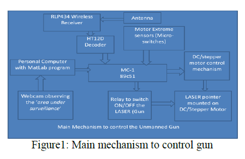 |
| The image is segmented into 16 quadrants and then finds a high intensity quadrant to the microcontroller via the Serial/Parallel port of the PC and then it rotates the motor into a particular direction and starts triggering for a while and stops until the next intruder comes. |
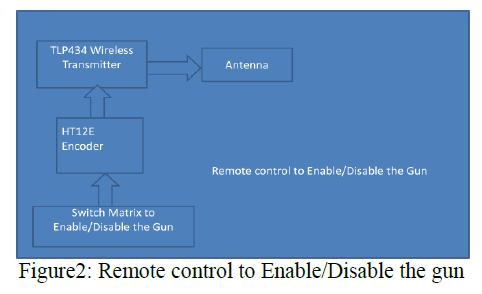 |
| This mechanism will be online i.e. the gun will continuously be pointing in the direction of the intruder. Further depending on range (distance from the gun) (fixed range in this project) the gun can be activated and a Laser pointer will be switched ON to depict „shooting the targetâÃâ¬ÃŸ. A wireless control employing TLP/RLP 434 devices whose wireless range can be extended upto 250Fts is used to enable/disable the gun using a remote. |
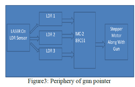 |
| Further to take care of certain conditions when the enemy also visits the post in white dress and the device might fail to detect him, we propose a LASER sensors deployment along the periphery which will be able to identify in case anything has been present in front of it for a certain amount of time. |
III.HARDWARE IMPLEMENTATION |
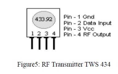
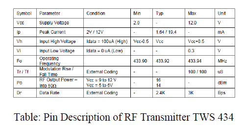
| 433MHz and the transmitter and the receiver module in the robotic module and the control unit respectively operate at the frequency of 316MHz.The RF transmitter in the control unit is used to transmit the signals which control the robotic moduleâÃâ¬ÃŸs operations. The RF transmitter and receiver are used both in the control unit as well as in the robotic module. The RF transmitter and receiver in the transmitter and receiver module respectively operate at the frequency of |
 |
 |
B. RF receiver |
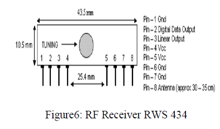
| The RF receiver in the transmitter module receives the distance related information transmitted by the robotic module. The microcontroller is used to display the distance on the LCD module. The receiver in the robotic module receives the control signals transmitted by the control unit which are used to control various functions of the robot. The figure below shows the pin out diagram of the RF receiver. |
 |
 |
| C. RX: The Receiver consists of RLP434 which is a Reciever from LAIPAC company and will be able to receive all the data coming from the TLP434 serially modulated using ASK Modulation. This information will be sent to the HT12D „decoderâÃâ¬ÃŸ IC which will then be able to decode the information and provide a 4 bit TTL output |
| D.TX: The transmitter consists of a TLP434 which is a transmitter from LAIPAC company and will be used in our project to send the encoded data to the receiver. The encoded data is received from the HT12E „ EncoderâÃâ¬ÃŸ IC which in turn receives it from the 20 Pin variant 89C2051 on the remote. |
| E. HT12D: The 212 decoders are a series of CMOS LSIs for remote control system applications. They are paired with Holtek_s 212 series of encoders (refer to the encoder/decoder cross reference table). For proper operation, a pair of encoder/decoder with the same number of addresses and data format should be chosen.The decoders receive serial addresses and data from a programmed 212 series of encoders that are transmitted by a carrier using an RF or an IR transmission medium. |
| F. HT12E: The 212 encoders are a series of CMOS LSIs for remote control system applications. They are capable of encoding information which consists of N address bits and 12_N data bits. Each address/ data input can be set to one of the two logic states. The programmed addresses/data are transmitted together with the header bits via an RF or an infrared transmission medium upon receipt of a trigger signal. The capability to select a TE trigger on the HT12E or a DATA trigger on the HT12A further enhances the application flexibility of the 212 series of encoders. |
| G. Stepper Motor: A stepper motor is a widely used device that translates electrical pulses into mechanical movement The stepper motor is used for position control in applications such as disk drivers, dot matrix printers, and robotics, etc. Every stepper motor has a permanent magnet rotor (also called the shaft) surrounded by a stator.The most common |
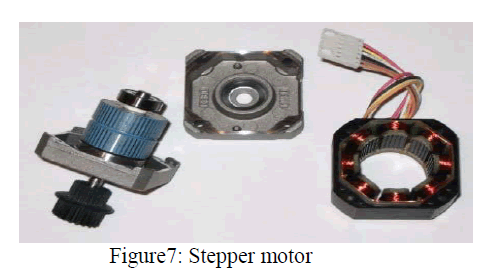 |
| Stepper motors have four stator windings that are paired with a center-tapped common.This type of stepper motor is commonly referred to as a four-phase stepper motor. |
| H. Device controller with driver (ULN2003): The ULN2003 is comprised of seven high voltage , high current NPN Darlington transistor pairs. All units feature common emitter, open collector outputs. To maximize their effectiveness, these units contain suppression diodes for inductive loads and appropriate emitter base resistor for leakage. |
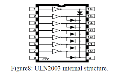 |
| The ULN2003 offers a solution to a great many interface needs, including solenoids, relays, lamps, small motors, and LEDs. Applications requiring sink currents beyond the capability of a single output may be accommodated by a paralleling the outputs. |
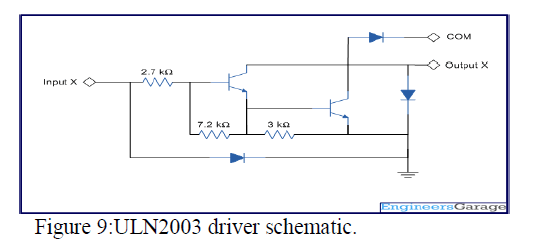 |
| I. Relay Switch: A relay is an electrically operated switch. Current flowing through the coil of the relay creates a magnetic field which attracts a lever and changes the switch contact. Relays allow one circuit to switch a second circuit which can be completely separate from the first. There is no electrical connection inside the relay between the two circuits; the link is magnetic and mechanical. |
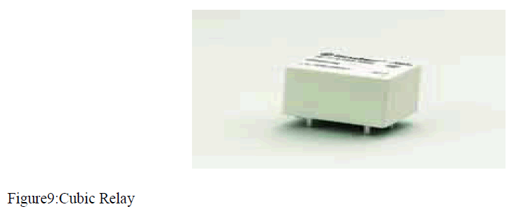 |
| A relay is an electrical switch that opens and closes under the control of another electrical circuit, the switch is operated by an electromagnet to open or close one or many set of contacts. The movement either makes or breaks a connection with a fixed contact. Relay has 5 pins normally connect(NC),normally open(NO),C1,C2 and pole. NC is given 5V , NO is grounded, C1 is given 12V, C2 is connected to microcontroller, pole is connected to motor. A relay is an electrically controllable switch. It allows the isolation of 2 separate sections of a system with 2 different voltage sources, one such relay is called an electromagnetic or electromechanical relay. |
| J. MAX 232: UART (Universal Asynchronous Receiver Transmitter) or USART (Universal Synchronous Asynchronous Receiver Transmitter) are one of the basic interface which you will find in almost all the controllers available in the market till date. This interface provide a cost effective simple and reliable communication between one controller to another controller or between a controller and PC. |
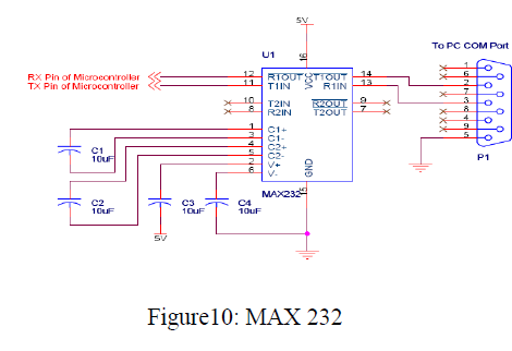 |
| Usually all the digital ICs work on TTL or CMOS voltage levels which cannot be used to communicate over RS-232 protocol. So a voltage or level converter is needed which can convert TTL to RS232 and RS232 to TTL voltage levels. |
IV. SOFTWARE IMPLEMENTATION |
| KEIL Software: Keil Software provides the premier development tools for the 8051 family of microcontrollers. The Keil Software 8051 development tools are use to compile c code, assemble assembly source files, link and locate object modules and libraries, create HEX files, and target program μ Vision2 for Windows is an Integrated development environment that combines project management, source code editing, and program debugging in one single, powerful environment.Keil Software delivers software in two types of kits; |
| Evaluation Kits includes evaluation versions of 8051 tools along with this userâÃâ¬ÃŸs guide.The tools in the evaluation kit generates applications upto 2kbytes in size.Production Kits includes the unlimited versions of 8051 tools along with a full manual set .The production kit includes 1 year of free technical support and product updates. |
| MATLAB Software: MATLAB is a program for doing numerical computation. It is originally designed for solving linear algebra type problems using matrices. MATLAB has been expanded and has built-in- functions for solving problems requiring data analysis, signal processing, optimization, and several other types of scientific computation. The MATLAB environment is command oriented somewhat like UNIX. A prompt appears on the screen and a MATLAB statement can be entered. When the <ENTER> key is pressed, the statement is executed, and another prompt appears. |
| MATLAB image types |
| ïÃÂö Indexed images: m-by-3 colour map |
| ïÃÂö Intensity images: [0,1] or uint8 |
| ïÃÂö Binary images: {0,1} |
| ïÃÂö RGB images: m-by-n-by-3 |
Indexed images: |
| [x,map] = imread („trees.tifâÃâ¬ÃŸ); |
| imshow(x,map); |
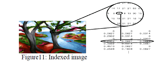 |
Intensity images: |
| Image = ind2gray(x,map); |
| Imshow(image); |
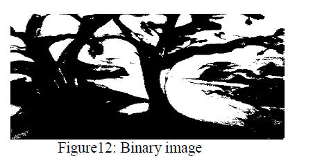 |
RGB image: |
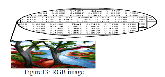 |
| Image Acquisition: The image acquisition toolbox software implements an object oriented approach to image acquisition. Using toolbox function, one can create an object that represents the connection between MATLAB and specific image acquisition devices. |
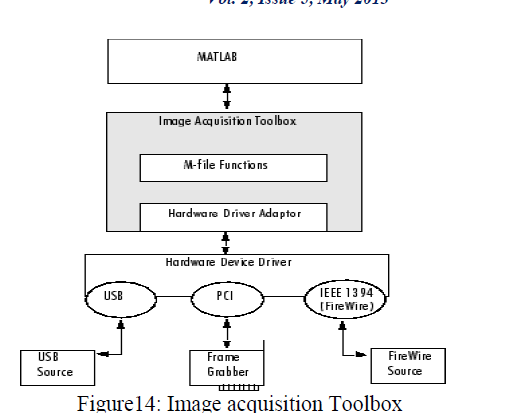 |
| Using properties of the object one can control various aspects of acquisition process, such as the amount of video that want to capture. Once connection is established to a device, one can acquire image data by executing a trigger. In the toolbox all image acquisition is initiated by a trigger. The toolbox supports several types of trigger that let one control when an acquisition takes place. |
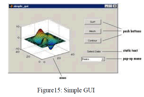
| Graphical user interface (GUI): A graphical user interface (GUI) is a graphical display that contains devices that enables a user to perform interactive tasks . To perform these tasks, the user of GUI does not have to create a script or type commands at the command line . The GUI components can be menus, toolbars, pushbuttons, radio buttons, list boxes, and sliders. In Matlab ,a GUI can also display data in tabular form or as plots and group related components.The following figure illustrates a simple GUI : |
 |
| This product is completely sound, and has great market value. Concerned with the threats to the nation at the border with enemies in blasting the base camps, weapons, machinery and lot of warfare materials of high cost. This modern is built in such a way that it is going to acquire the data by a high resolution camera and processes, and then makes a suit at the enemy. Hence we can say that this product is best suitable for boarder security and even in some secure areas where national integrity and safety is major issue. |
References |
|