ISSN ONLINE(2320-9801) PRINT (2320-9798)
ISSN ONLINE(2320-9801) PRINT (2320-9798)
Ashish Jadhav1, Mahesh Kumbhar2, Mahesh Walunjkar3
|
| Related article at Pubmed, Scholar Google |
Visit for more related articles at International Journal of Innovative Research in Computer and Communication Engineering
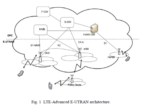
This paper summarizes how one can make use of 4th generation of wireless communication to control Ground Combat Vehicle which is the Army's replacement program for armoured fighting vehicles in Heavy and Stryker brigade combat teams. Robotics in army is an interesting field where every engineer can showcase his creative and technical skills. As the development of individual and cooperating autonomous robots advances, the need for robust and reliable communication method becomes apparent. This paper summarizes a the feasibility of implementing Dual-Tone, Multi-Frequency (DTMF) as an alternative mean of robotic communication to Radio Frequency (RF) for controlling the Ground Combat Vehicle which will remove the need of human being to be involved physically in the battle. The user in order to control the vehicle should make a video call to the 4G enabled phone attached in the Vehicle, from any another 4G enabled phone, which can send DTMF tones by pressing the numeric buttons and can view the video output. The cell phone in the vehicle is kept in auto answer mode. So, after a ring the cell phone accepts the call and starts video transmission. This article provides an in-depth view on the technologies being considered for Long Term Evolution-Advanced (LTE-Advanced). First generation (1G) wireless telecommunication is the term related to analog phones that are now collector’s items - introduced the cellular architecture that is still being offered by most wireless companies today. Second generation (2G) wireless supported more users within a cell by using digital technology, which allowed many callers to use the same multiplexed channel. But 2G was still primarily meant for voice communications, not data, except some very low data-rate features, like short messaging service (SMS). Socalled 2.5G allowed carriers to increase data rates with a software upgrade at the base transceivers stations (BTS), as long as consumers purchased new phones too. Third generation (3G) wireless offers the promise of greater bandwidth, basically bigger data pipes to users, which will allow them to send and receive more information.
Keywords |
| Ground Combat Vehicle, DTMF technology, 4G wireless communication, Digital telephony. |
INTRODUCTION |
| Fourth generation (4G) wireless was originally conceived by the Defence Advanced Research Projects Agency (DARPA), the same organization that developed the wired internet. It is not surprising, then, that DARPA chose the same distributed architecture for the wireless Internet that had proven so successful in the wired Internet. Although experts and policymakers have yet to agree on all the aspects of 4G wireless, two characteristics have emerged as all but certain components of 4G: end-to-end Internet Protocol (IP), and peer-to-peer networking. An all IP network makes sense because consumers will want to use the same data applications they are used to in wired networks. A peer-to-peer network, where every device is both a transceiver and a router/repeater for other devices in the network, eliminates this “star architecture” weakness of cellular network, because the elimination of a single node does not disable the network. The final definition of “4G” will have to include something as simple as this: if a consumer can do it at home or in the office while wired to the Internet, that consumer must be able to do it wirelessly in a fully mobile environment [1]. |
| The fourth generation (4G) of wireless cellular systems has been a topic of interest for quite a long time, probably since the formal definition of third generation (3G) systems was officially completed by the International Telecommunications Union Radio communication Sector (ITU-R) in 1997. A set of requirements was specified by the ITU-R regarding minimum peak user data rates in different environments through what is known as the International Mobile Telecommunications 2000 project (IMT-2000). The requirements included 2048 kbps for an indoor office, 384 kbps for outdoor to indoor pedestrian environments, 144 kbps for vehicular connections, and 9.6 kbps for satellite connections |
II. NETWORK ARCHITECTURE |
| An easy way to comply with the conference paper formatting requirements is to use this document as a template and simply type your text into it. |
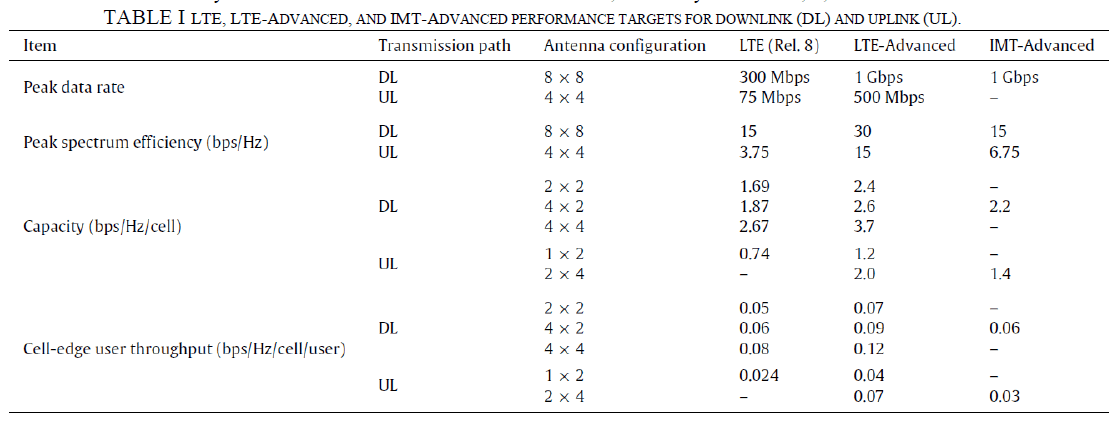
| 3GPP specified in its Release 8 the elements and requirements of the EPS architecture that will serve as a basis for the next-generation networks. The specifications contain two major work items, namely LTE and SAE that led to the specification of the Evolved Packet Core (EPC), Evolved Universal Terrestrial Radio Access Network (E-UTRAN), and Evolved Universal Terrestrial Radio Access (E-UTRA), each of which corresponds to the core network, radio access network, and air interface of the whole system, respectively. The EPS provides IP connectivity between a User Equipment (UE) and an external packet data network using E-UTRAN. In Fig. 1, we provide an overview of the EPS, other legacy Packet and Circuit Switched elements and 3GPP RANs, along with the most important interfaces. In the services network, only the Policy and Charging Rules Function (PCRF) and the Home Subscriber Server (HSS) are included, for simplicity. |
| In the context of 4G systems, both the air interface and the radio access network are being enhanced or redefined, but so far the core network architecture, i.e. the EPC, is not undergoing major changes from the already standardized SAE architecture. Therefore, in this section we give an overview of the E-UTRAN architecture and functionalities defined for the LTE-Advanced systems and the main EPC node functionalities, shared by Releases 8, 9, and 10. |
 |
 |
A. LTE-Advanced E-UTRAN overview |
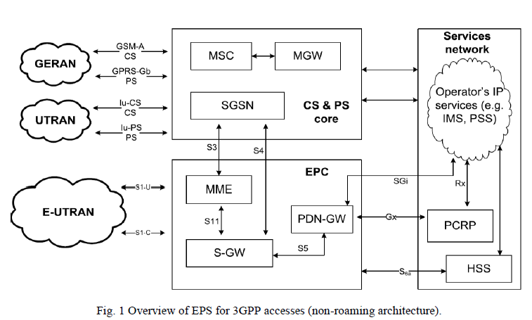
| In Fig. 2, we show the architecture of E-UTRAN for LTE Advanced. The core part in the E-UTRAN architecture is the enhanced Node B (eNodeB or eNB), which provides the air interface with user plane and control plane protocol terminations towards the UE. Each of the eNBs is a logical component that serves one or several E-UTRAN cells, and the interface interconnecting the eNBs is called the X2 interface. Additionally, Home eNBs (HeNBs, also called femtocells), which are eNBs of lower cost for indoor coverage improvement, can be connected to the EPC directly or via a gateway that provides additional support for a large number of HeNBs.1 |
 |
B. Evolved Packet Core overview |
| The EPC is a flat all-IP-based core network that can be accessed through 3GPP radio access (UMTS, HSPA, HSPA+, LTE) and non-3GPP radio access (e.g. WiMAX, WLAN), allowing handover procedures within and between both access types. The access flexibility to the EPC is attractive for operators since it enables them to have a single core through which different services are supported. |
III. DTMF TECHNOLOGY |
| The DTMF technology is associated with digital telephony and provides two selected O/P frequencies (One high band and one low band). The DTMF technique consist of 16 common alphanumeric characters (0-9, A-D, *, #) on the telephone. Each characters is uniquely referenced by selecting one of the four low band frequencies associated with the matrix rows, coupled with selecting one of the four high band frequencies associated with the matrix columns [2]. |
 |
| Corresponds to each character, there is unique tone frequency given by, |
 |
IV. WORKING STEPS |
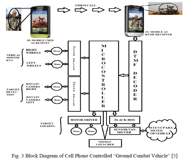
| In the article the Ground Combat Vehicle is controlled by a mobile (with 4G support) which makes a video call to the mobile phone (with 4G support) attached to the vehicle as shown in Fig. 3. In the course of a video call if any button is pressed a tone corresponding to the button pressed is heard at the other end of the call. This tone is called DTMF tone. The vehicle perceives this DTMF tone with the help of phone stacked in the vehicle. The processing of received DTMF tone is done by Atmega 32 microcontroller with the help of DTMF decoder. The decoder decodes the DTMF tone into its equivalent binary digit and this binary number us sent to the microcontroller. The microcontroller is pre-programmed to take a decision for any given input. The microcontroller outputs its decision to motor driver to drive the motors in order to have forward or backward motion or a turn. Any mobile which makes a video call to the mobile phone stacked in the tank will acts as remote. So, this is a simple robotic project which even does not require the construction of receiver and transmitter kits, but has an innovated application of cell phone, 3G and robust control [3]. |
A. Proposed Block Diagram |
ïÃâ÷ Remote Mobile |
| The remote mobile is with the operator which is used to send DTMF tones on the other mobile on the vehicle. |
| ïÃâ÷ Receiver Mobile |
| It is used to receive DTMF signals transmitted by the remote mobile. |
ïÃâ÷ DTMF Decoder |
| The decoder decodes the DTMF tone into its equivalent Binary Digits & this binary Number is send to the microcontroller. It acts as an intermediate device between receiver mobile and microcontroller to decode the DTMF tone in a compatible signal accepted by microcontroller. |
ïÃâ÷ Microcontroller |
| It processes on the DTMF signal and gives corresponding actions which is to be taken by the motor driver on which the direction is controlled by the operator. |
| The Microcontroller is pre-programmed to take a decision for any given input & outputs its decision to motor drivers in order to drive the motors for forward or backward motion or a turn. |
 |
ïÃâ÷ Motor Driver |
| In the four-wheel drive system the two-motors on a side are controlled in parallel. So a single L293D Driver IC can drive the rover. |
V. CIRCUIT SCHEMATIC |
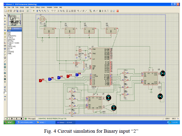
| The actual work of project implementation with its design started with the real time simulation. Here are some results of different trials that taken while designing the PCB Shown in Fig. 4 for different key strokes. |
| Simulation proved to be a very handy & easy-to-use tool for the PCB layout process. Many of its features were utilized leading to an accurate & efficient design. It has Design Error Check & Electrical Rule Check tools which proved to be helpful in the design. It is loaded with a huge component list (Library) that is categorized in various libraries for giving simplicity. Placement of components is also very easy & they can be rotated in 360âÃÂð to customize the design. |
 |
RESULTS |
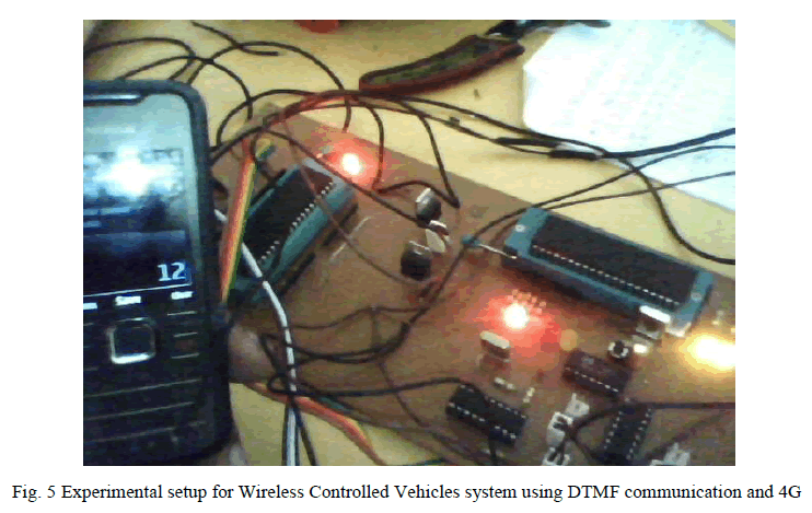
| The system discussed above is versatile for controlling the vehicles by combining the DTMF and 4G technology. Experimental set up required for the same is as shown in figure 2 [5]. |
 |
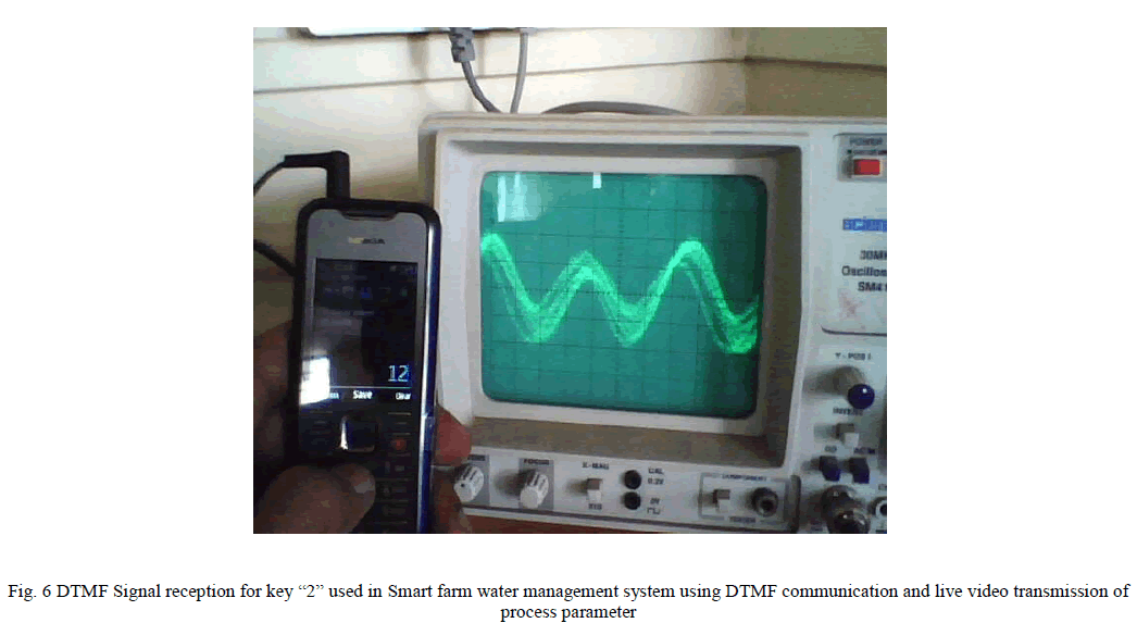
| When the user pushes a button on remote mobile it will be sent to other end. The reception of signal is indicated in figure 8 [5]. |
 |
VII. CONCLUSIONS |
| LTE-Advanced, the backward-compatible enhancement of LTE Release 8, will be fully specified in 3GPP Release 10. It has already been submitted as 3GPP’s 4G candidate radio interface technology to ITU-R. We have described its main technologies: carrier aggregation, enhanced MIMO, cooperative multipoint transmission and reception, and relays. For each one, we have examined their benefits, challenges, and some existing approaches to tackle these challenges. However, several issues in each of them are still open and require further research. |
| It is the combination of these technologies, and not just a single one, that will enable achieving the target performance requirements established by IMT-Advanced. The development and integration of these elements will not end with 3GPP Release 10, but will provide the starting point for their implementation. |
| In addition to the elements that we have examined in this paper, it is also expected that the use of femtocells, selforganizing networks, and energy management systems will drive the evolution of current and future mobile wireless networks. From this experimentation we can conclude that it is infeasible and inefficient to implement acoustic communication method for DTMF technology. And it is possible to produce an alternative way to the RF communication by using DTMF and mobile handsets acting as transceiver. |
| As interest in robotics continues to grow, robots are increasingly being integrated into everyday life. The results of this integration are end-users possessing less and less technical knowledge of the technology. For example, consider the application of mobile robots in the health care industry, where the intended end users are patients themselves. In this case, the need for simplified, reliable, and user-friendly robot designs is of almost importance. So this project reduces the mystery of robotics to average user. |
| Advance capability of robotics in Military Technology can be verified. From this investigation we should conclude that it is possible to produce an alternative method to RF communication and which will reduces the amount of RF noise in the environment. |
VIII. FUTURE SCOPE |
| After carrying out the present work, it is found that the following things can be added as an extension to this work. As experimental work is carried out on small scale model because of limitations of battery capacity, one can go for full scale model using Ground Combat Vehicle (GCV) in Army; |
| ïÃâ÷ Experimental work is carried out in laboratory condition; one can go for actual road condition test; |
| ïÃâ÷ Solar cells can be used to power up the GCV. This will be the added advantage in terms of power management. |
References |
|