ISSN ONLINE(2278-8875) PRINT (2320-3765)
ISSN ONLINE(2278-8875) PRINT (2320-3765)
Pavan Kumar Shukla1 , Arnab Chakraborty2, R.K. Singh3
|
| Related article at Pubmed, Scholar Google |
Visit for more related articles at International Journal of Advanced Research in Electrical, Electronics and Instrumentation Engineering
In this paper, the various favorable channel characteristics for optical OFDM have been discussed and presented .When we are using an indoor or outdoor wireless optical channel for the transmission of optical OFDM signals ,then an antenna system of 60 GHz freq. range is required. So for these particular applications of optical OFDM system a Di-pole antenna is proposed .Its design considerations and the simulated results are given in this paper. Performance of the proposed antenna is analyzed in terms of the reflection loss and its radiation pattern. Here a wireless system of super-broadband 60 GHz photonic optical OFDM system .In this paper we also used a cascaded optical RF and data modulation approach in which the advanced photonic components and a highspectral efficient QAM-OFDM modulation format is utilized. Finally we realized a compact 60 GHz photonic wireless system having a better spectral efficiency. We may also achieve very high data throughputs by making use of the 7 GHz spectral bandwidth in the 60 GHz band.
Keywords |
| Wireless Infrared communications, Dipole antenna Design of 60 GHz, Optical OFDM System, Intensity Modulation |
INTRODUCTION |
| In the new era of digital and optical communications the emergence of portable information terminals in work and living environments is accelerating the introduction of wireless digital links and local area networks (LAN’s). Portable terminals should have access to all of the services that are available on high-speed wired networks. Unlike their wired counterparts, portable devices are subject to severe limitations on power consumption, size and weight. The desire for inexpensive, high-speed links satisfying these requirements has motivated recent interest in infrared wireless communication [1]. If we use infrared as a medium for shortrange, indoor communication, it offers several significant advantages over radio. Infrared emitters and detectors capable of high speed operation are available at low cost. The infrared spectral region offers a virtually unlimited bandwidth that is unregulated worldwide. Infrared and visible light are close together in wavelength, and they exhibit qualitatively similar behavior. Both are absorbed by dark objects, diffusely reflected by light-colored objects, and directionally reflected from shiny surfaces. Both types of light penetrate through glass, but not through walls or other opaque barriers, so that infrared transmissions are confined to the room in which they originate. This signal confinement makes it easy to secure transmissions against casual eavesdropping, and it prevents interference between links operating in different rooms. Thus, infrared wireless LAN’s can potentially achieve a very high aggregate capacity, and their design may be simplified, since transmissions in different rooms need not be coordinated. |
| When an infrared link employs intensity modulation with direct detection (IM/DD), the short carrier wavelength and large-area, square-law detector lead to efficient spatial diversity that prevents multipath fading. By contrast, radio links are typically subject to large fluctuations in received signal magnitude and phase. Radio and infrared are complementary transmission media, and different applications favor the use of one medium or the other. Radio is favored in applications where user mobility must be maximized or transmission through walls or over long ranges is required and may be favored when transmitter power consumption must be minimized. Infrared is favored for short-range applications in which per-link bit rate and aggregate system capacity must be maximized, cost must be minimized, international compatibility is required, or receiver signal-processing complexity must be minimized. Infrared links may employ various designs, and it is convenient to classify them according to two criteria. Directed links employ directional transmitters and receivers, which must be aimed in order to establish a link, while nondirected links, employ wide angle transmitters and receivers, alleviating the need for such pointing. Directed link design maximizes power efficiency, since it minimizes path loss and reception of ambient light noise. On the other hand, nondirected links may be more convenient to use, particularly for mobile terminals, since they do not require aiming of the transmitter or receiver. It is also possible to establish hybrid links, which combine transmitters and receivers having different degrees of directionality. The second classification criterion relates to whether the link relies upon the existence of an uninterrupted line-of sight (LOS) path between the transmitter and receiver. LOS links rely upon such a path, while non-LOS links generally rely upon reflection of the light from the ceiling or some other diffusely reflecting surface. LOS link design maximizes power efficiency and minimizes multi path distortion. Non-LOS link design increases link robustness and ease of use, allowing the link to operate even when barriers, such as people or cubicle partitions, stand between the transmitter and receiver. The greatest robustness and ease of use are achieved by the non directed-non-LOS link design, which is often referred to as a diffuse link. |
II. SYSTEM ARCHITECTURE OF OPTICAL OFDM |
| The major problems related to outdoor or indoor wireless optical communications are belonging to intersymbol interference. This interference greatly degrades the quality of transmission, and its effects become more severe in case of diffuse links. This is a serious problem, especially in the case of ultra high speed optical wireless LAN such as 1 Gbps or more. To combat the ISI effect, parallel transmission technique is one of the possible solutions [2]. Parallel transmission lowers the data rate per channel, which consequently diminishes the ISI effects. Optical orthogonal frequency division multiplexing is proposed to reduce the effects of ISI in optical communications and thus improve the quality of transmission [3]. In an OFDM system, a serial high data rate data stream is split up into a set of low data rate sub-streams. The total channel bandwidth is divided into a number of orthogonal frequency sub-channels and each of these low data rate sub streams is modulated on a separate sub-channel. The orthogonality is achieved by selecting a special equidistant set of discrete carrier frequencies. It can be shown that, this operation is conveniently performed by the Inverse Fast Fourier Transforms (IFFT). At the receiver, the Fast Fourier Transform (FFT) is used to de-multiplex the parallel data streams [2]. In current research, optical orthogonal frequency division multiplexing is proposed to combat dispersion in optical fiber media [4]. The authors in [4, 5] presented the theoretical basis for coherent optical OFDM systems in direct up/down conversion architecture. In [6], the authors showed that Optical Orthogonal Frequency Division Multiplexing outperformed RZ-OOK transmission in high-speed optical communication systems in terms of transmission distance and spectral efficiency. |
| In the above mentioned researches, optical OFDM was accomplished by first performing the OFDM electronically using DSP kits then converting to optical signals. In our paper, we propose all optical OFDM system in diffuse wireless optical channels. The proposed system will be explained with design considerations and analytical evaluations in coming sections. The optical OFDM system starts with the serial high data rate input which then passes to a serial to parallel (S/P) block similar to the conventional OFDM system. The all optical OFDM system differs from the conventional OFDM system in the conversion of the low data rate parallel sub stream into optical signals and performing the IFFT techniques optically rather than electrically .Recent progress of digital signal processing circuit has made it possible to implement the IFFT in wireless communication systems. However, this scheme cannot be applied to the optical communications as the data rate is beyond the digital signal processing speed capabilities. The low rate parallel sub stream is converted to an optical signal using electrical to optical conversion. This is followed by modulating each optical sub stream using any type of optical modulation techniques as discussed in [7]. All the optical modulators in Figure 2 have the same optical wavelength and are using the same DFB lasers as light sources. The optical conversion and modulation is called base band optical modulator. The base band optical modulator is followed by an optical IFFT [8], which consists of fiber delay lines and phase shifters. The number of fiber delay lines is equal to the parallel sub streams which also correspond to number of sub-carriers in the conventional OFDM. The delay lines realize orthogonality by having different lengths. The phase shifters implement the different sub-carriers that are orthogonal to each other and thus will be similar to IFFT done by DSP kits. |
| In fact this is a system in which optical signals are converted in a difficult manner as it is difficult to optically copy and paste. This can be overcome using optical gates and what we called optical cyclic prefix. The optical cyclic prefix is divided into two branches using an optical coupler; the first branch is a fiber delay line and the second branch is an optical switch. The optical switch is used to copy the last part of the active ray period and paste it to the front of the optical ray by an optical coupler after it is delayed by a symbol period. The delay is done using the first branch after the coupler. Optical transmitter is used to modulate the OOFDM signal to be suitable for transmission in wireless optical channel. At the receiver side, optical OFDM signal is detected by an optical receiver and then the optical cyclic prefix is removed. The IFFT and optical demodulator are performed to get the corresponding transmitted bit streams. |
III. OFDM OVER INDOOR WIRELESS OPTICAL CHANNEL |
A. Optical channel model |
| Basically the optical channel model should be one which may be used to estimate the impulse response of IR wireless indoor channels .Here a unique algorithm [3] is given in which every ray is generated at the emitter position with a probability distribution equal to its radiation pattern. The power of each generate ray is initially the source power (1 W) divided by the number of rays used to discretise the source. When a ray impinges on a surface, the reflection point is converted into a new optical source, thus a new ray is generated with a probability distribution provided by the reflection pattern of that surface. The process continues during the simulation time. After each reflection, the power of the ray is reduced by the reflection coefficient (r) of the surface and the reflected power which reaches the receiver ( pick ith ray, kth time interval) is computed. Phong’s model was used to describe the reflection pattern of surfaces [14]. This model is able to approximate the behavior of those surfaces that present a strong secular component: it takes into account the reflection pattern as the sum of both diffuse and specular components. Therefore, surface characteristics are defined by two new parameters: the percentage of incident signal that is reflected diffusely rd and the directivity of the specular component of the reflection m. The total received power in the kth time interval (width Dt) is computed as the sum of the power of the Nk rays that contribute in that interval. |
 |
B. Wireless optical OFDM system |
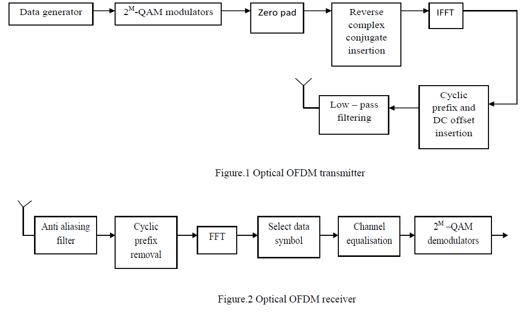
| Here we may give the individual features of the optical OFDM transmitter and receiver. Their main building blocks are given in figure 1 and figure 2.The wireless optical OFDM system transmitter is shown in figure 1where the data bits each of duration Tb are generated and modulated by P 2M-QAM modulators (P carriers). Then, N-P zeros (one of them before, corresponding to DC value) are padded to the P symbols generated by the modulators, and the complex conjugate of the mirror of the word of N symbols is added to the latter before computing IFFT. The outgoing IFFT symbol is a real sequence of 2N points and it can drive directly the light source after adding an appropriate DC offset to avoid lower clipping. Moreover, a cyclic prefix is inserted (L - 2N Samples extension) to combat ISI. The symbol duration is Ts = MPTb seconds, where L samples are transmitted. This transmitted signal is distorted by channel response (channel plus transmitter low-pass and receiver anti-aliasing filters) and corrupted by noise (channel noise, preamplifier thermal noise and photodiode shot noise). The overall noise process is modeled as zero-mean additive white Gaussian noise (AWGN) with two-sided power spectral density N0/2: We assume that the receiver is synchronized to the LOS signal. Once the corrupted cyclic prefix is removed, the FFT of 2N points is computed by the receiver. Only the first P points (after DC value) are considered and channel equalization is performed over them. It is a very simple operation. A known training sequence (Xp; p = 1,2, . . . ,P) is transmitted owing to the slowly time-varying nature of wireless optical channels, and the channel response of each sub-band (Hp) can be estimated from the P received symbols (Yp) as follows |
 |
| This value can be used to outweigh the distorting channel effects before symbol demodulation. . Note that Hp’ values are distorted by noise and, therefore, several training sequences can be transmitted and then we can use the mean values of the estimates for a better channel characterization. |
 |
III. LONG-DISTANCE OPTICAL WIRELESS SYSTEMS USING IM/DD |
| In general terms an outdoor long-distance optical wireless system may be divided into three parts: transmitter, propagation path and receiver. In order to accommodate the high-speed operation, the transmitter usually utilizes semiconductor lasers with broad bandwidth and high launch power. The receiver employs a trans impedance design, which makes a good compromise between bandwidth and noise, combined with bootstrapping that reduces the effective capacitance of the photodiode. |
| Typical (bootstrapping) receivers use either (optically pre-amplified) PIN or avalanche photodiodes (APD) of different dimensions. IM/DD using OOK is widely deployed to modulate the signals. Fig. 3 illustrates a typical set-up of a long-distance pointto- point optical wireless system [4]. The power budget and raw-data performance of a LOS optical wireless link are subject to atmospheric loss along the propagation path, which includes free space loss, clear air absorption, scattering, refraction and atmospheric turbulence (or scintillation). Free space loss defines the proportion of optical power arriving at the receiver that is effectively captured within the receiver’s aperture (see Fig. 3), and exists in all indoor and outdoor systems. Other forms of channel impairment are experienced only by outdoor systems. Air absorption, scattering and refraction are closely related to weather (e.g., fog, mist and snow). Nevertheless, field tests conducted in major cities around the world show that the atmospheric attenuation due to these factors is consistently low [5]. |
| The dominant impairment to long-distance outdoor systems (500m to a few kilometers) is atmospheric turbulence, which occurs as a result of the variation in the refractive index due to in homogeneities in temperature and pressure fluctuations. Atmospheric turbulence can be physically described by Kolmogorov theory [1], [2]. It causes the optical signal to scatter preferentially at very shallow angles in the direction of propagation, which, upon multiple signals (multiple laser strands), causes them to experience different phase shifts at they arrive simultaneously at the receiver. This in turns results in random amplitude fluctuation of the detected signal. |
 |
IV. PROPOSED 60 GHz ANTENNA FOR OPTICAL OFDM APPLICATIONS |
| For the specific applications of optical OFDM systems we propose a 60 GHz antenna which will be capable to transmit and receive the optical OFDM signals. Here we are using a system configuration of the 60 GHz photonic wireless transmission system. In general, the system consists of an optical mm-wave carrier generator unit with a subsequent broadband data modulation, a photonic wireless transmitter and a coherent wireless receiver. Traditionally, all-electronic wireless backhauling systems where operated in the microwave domain but because of the congestion in the microwave bands and because of regulatory constraints, their capacity is limited to about a maximum of 200-600 Mbit/s. A solution for multi-gigabit wireless systems is seen shifting the carrier frequency to the mm-wave frequency bands where sufficient bandwidth was made available for broadband wireless services by regulatory agencies worldwide. The 7 GHz spectrum in the 60 GHz band (57-64 GHz) which is regulated worldwide for unlicensed wireless services is a promising candidate for future multi-gigabit wireless systems. However, realizing such a broadband wireless communication system presents many technical challenges owing to the high carrier frequencies, the wide bandwidths used and the higher loss due to oxygen absorption. In comparison to all-electronic wireless systems, photonic solutions generally have the edge whenever high aggregate bit rates and/or long transmission distances are involved and consequently most broadband wireless demonstrations to date employed photonic approaches [5]. We have previously reported on a photonic broadband 12.5 Gbit/s wireless system operating at 60 GHz using ASK modulation [7]. However, in that case the spectral efficiency was below 0.5 bit/s/Hz meaning that within the regulated bandwidth from 57 GHz to 64 GHz it was only possible to transmit a maximum throughput of about 3.5 Gbit/s. In this paper, we report on a compact and high spectral efficient super-broadband photonic wireless system operating within the 7 GHz spectral bandwidth in the 60 GHz band. For the first time, we successfully demonstrate photonic wireless transmission of record data throughputs up to 27.04 Gbit/s using a 16-QAM OFDM modulation format resulting in a spectral efficiency as high as 3.86 bit/s/Hz. |
V. DESIGN AND SIMULATED RESULTS |
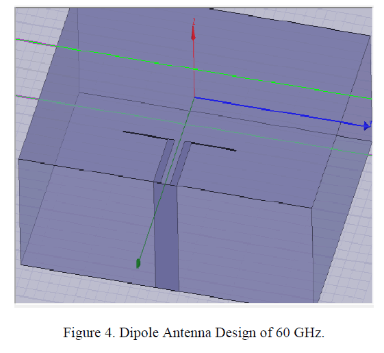
| The proposed design of a dipole antenna of 60 GHz consisting of a substrate of Gallium arsenide(GaAs) of a height of 0.5 mm. This is the material substrate which is available in the industrial applications and dimensions are the industrial standard dimensions. For the dipole antenna design we have calculated the dimension of the substrate as length x= 4 mm and width y=7 mm. There is one metal layer used in the design which is made up of the copper metal. The transmission lines dimensions may be given as width w =0.07 mm and length l = 0.05 mm. For the dipole dimensions we have calculated the length of the dipole as l=1.06 mm and the slot width is 0.0075 mm. The gap between the slots is kept as 0.01 mm. The design of the dipole antenna for 60 GHz. Is given in the following figure: |
 |
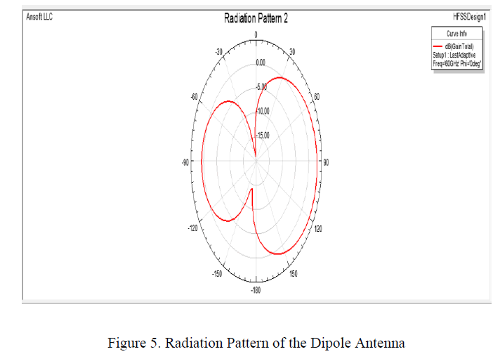
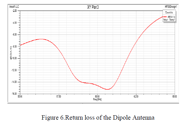
| The simulated results are obtained in the form of its radiation pattern and the return loss. These results are given in the following figures: |
 |
 |
| As we see in the radiation pattern diagram ,the gain of this Dipole Antenna is found as 2.3 dB. and the return loss as S11 = -15 dB .These results are calculated at the bandwidth of 5 GHz. Finally we found it suitable for the optical OFDM applications. As we have already described a system architecture of an optical OFDM System in which an antenna is suitable of the 60 GHz frequency range. This antenna may have various designs but the appropriate design with better radiation pattern and return loss is proposed here |
VI. CONCLUSION |
| In this paper we have investigated FSO communication as an alternative to RF-based communication technologies for optical OFDM applications. To enable mobile FSO communications, we proposed and developed a novel and suitable dipole antenna using patch antenna design in a CPW (Coplanar waveguide) configuration. These results are justified at a frequency range of 60 GHz. The radiation pattern major lobe sharpness may be increased in the form of its directivity. In this paper, we have presented a compact broadband photonic wireless 60 GHz transmission system based on a cascaded RF and data modulation approach. The modulation technique 8-QAM and 16-QAM OFDM formats we achieved record spectral efficiencies up to 3.86 t/s/Hz The results may be achieved by using an optical fiber with 12 m and 5 m wireless transmission .By increasing the transmit power and antenna gain, we expect being able to extend the wireless span up to a few 100 m given the measured wireless receiver sensitivity. |
References |
|