International Journal of Advanced Research in Electrical, Electronics and Instrumentation Engineering
ISSN ONLINE(2278-8875) PRINT (2320-3765)
ISSN ONLINE(2278-8875) PRINT (2320-3765)
R.De Four1, T.Wadi2
|
| Related article at Pubmed, Scholar Google |
Visit for more related articles at International Journal of Advanced Research in Electrical, Electronics and Instrumentation Engineering
Vector analysis is widely used for the analysis, modeling and control of electrical machines. The methodmakes use of vector currents, voltages and magnetic variables but does not represent them in an equivalent circuit of the machine. This paper presents the development of an equivalent circuit for an electromagnetic system consisting of scalar electrical, vector electrical and vector magnetic sections and shows the production of a vector current from its scalar counterpart that leads to the production of vector voltages on the magnetic axis of the system. Resultant current, voltage and magnetic variable vectors associated with a phase winding of a three-phase stator are also developed together with a single vector voltage equation of the system.
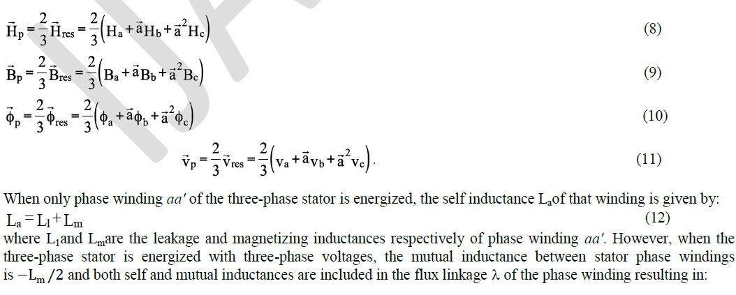
Keywords |
| Vector Analysis, Three-PhaseMotor Stator, Current and Voltage Vector, Equivalent Circuit. |
INTRODUCTION |
| Vector analysis is widely used for the analysis, modeling and control of electrical machines. The method makes use of vector currents, voltages and magnetic variables and reflects the physical phenomena occurring in the machines. The application of the vector method to the modeling, analysis and control of electrical machines has many advantages over other methods, some of which are: a reduction in system equations, easier machine control, a clear conceptualization of machine dynamics and easier analytical solution of dynamic transients of machine variables [1]. However, the material presented by Kovacs [2]for the vector analysis of a three-phase stator requires an equivalent circuit to demonstrate the generation of vector currents and the production of vector voltages to clearly formulate the vector method. |
| This paper presents the development of an equivalent circuit for an electromagnetic system consisting of scalar electrical, vector electrical and vector magnetic sections and shows the production of a vector current from its scalar counterpart that leads to the production of vector voltages on the magnetic axis of the system. A single voltage equation is also developed to represent all three windings of the three-phase stator. |
II. RELATED WORK |
| Vector analysis of electrical machines was developed by Kovacs and Racz[3] and is widely used in the modeling, transient analysis and control of these machines. The vector method has been documented in many books of reputed authors [4 – 7]and has been employed by Holtz [8 – 10] in the development of vector equations for electrical machines. However, the above application of the vector method in the analysis of electrical machines utilised vector currents, voltages and magnetic variables but did not represent them in an equivalent circuit of the machine. |
III.EQUIVALENT CIRCUIT OF A PHASE WINDING OF A THREE-PHASE MOTOR STATOR |
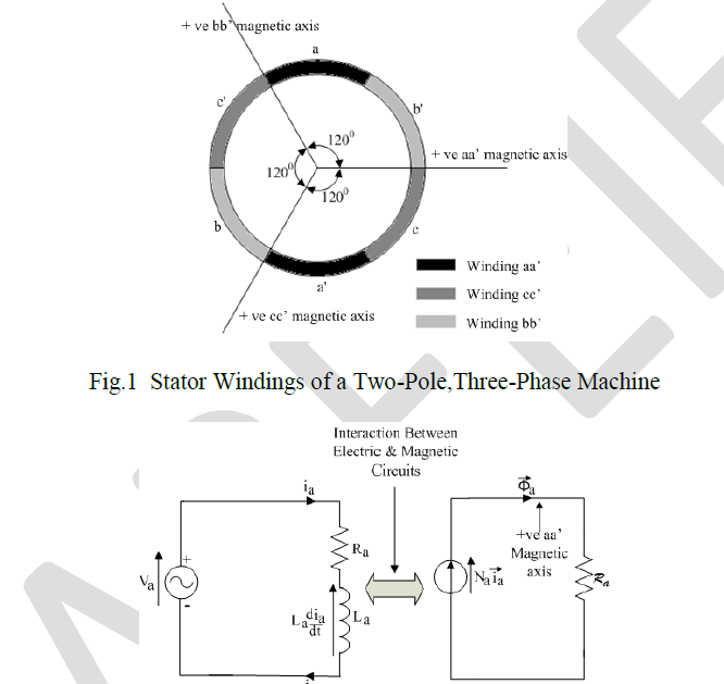
| A cross section of the stator windings of a two-pole, three-phase machine is shown in Fig. 1. The phase windings are shown to be displaced from each other by 1200 and the positive direction of current flowing through each winding is upwards through the non-primed side and downwards through the primed side. Using this convention of current flow through the windings, positive magnetic axes were developed for each phase winding, along which all magnetic quantities exists. |
| The analysis of electromagnetic systems has traditionally been performed with the production of two circuits, a scalar electrical circuit for electrical analysis and a vector magnetic circuit for magnetic analysis [11] as shown in Fig. 2, where Va represents supply voltage,ia winding current, Ra resistance of winding aa', La self inductance of winding aa',Rathe reluctance, Na number of turns in winding aa', and fluxÃÂÃ⢠aproduced by winding aa'. |
| However, quantities in the electrical circuit affect quantities in the magnetic circuit and vice versa. As a result of the dependence of both electrical and magnetic variables on each other, the development of an equivalent circuit containing both electrical and magnetic quantities would prove to be very useful in the analysis of electromagnetic systems. Since the three-phase stator is an electromagnetic system, then the development of an equivalent circuit containing both electrical and magnetic quantities would be a powerful tool in the vector analysis approach of this electromagnetic system. |
 |
| Fig. 2. Traditional Electrical and MagneticEquivalent Circuits of Phase Winding aa’ of The Three-Phase Stator |
| For this analysis, one phase winding of the three-phase stator, winding aa' was initially selected for analysis. This winding is represented in Fig. 3(a) by its center conductors and the currentiathrough the winding is in the positive direction. Fig. 3(a) is divided into two sections: electrical quantities are presented in the Scalar Electrical section and the other section containing the winding with its electricalscalar currentiaand magnetic variables, magnetic field intensityH a, flux density B a, flux ÃÂÃ⢠a, flux linkage λ a and current vector i aall on the positive (+ ve) magnetic axis of winding aa'. The electrical scalar current ia, which leaves the Scalar Electrical section of the circuit flows through the winding and produces vector magnetic field intensityH aalong the positive magnetic axis of winding aa'. This vector magnetic field intensityH amust be produced by a current vector i a on the positive magnetic axis of winding aa', hence, it can be said that the electrical scalar current iaon passing through winding aa' produces current vector i a on its positive magnetic axis. |
| magnetic axis. Fig. 3(b) consists of three sections: magnetic processes beginning and ending with current vector i a, a Scalar Electrical section as described earlier and a Vector Electrical section containing current vector i aseparating the above two sections. The vector electric current i a, on entering the Scalar Electrical section, produces a scalar current ia in the Scalar Electrical section, and the scalar electrical current iaon entering the Vector Electrical section, produces a vector electric current i a on the magnetic axis of winding aa' as shown in Fig. 3(b). Hence the magnetic axis of winding aa' completes the circuit making ia and |i a| of equal magnitudes. |
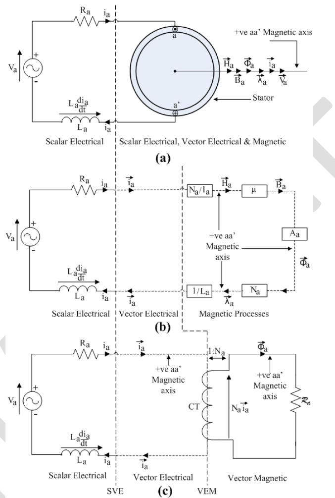 |
| Fig. 3. Equivalent Circuit of Three-Phase Stator with Winding aa' Energized(a) Scalar Electrical and Scalar Electrical, Vector Electrical & Magnetic Sections (b) Scalar Electrical, Vector Electrical Sections and Magnetic Processes (c) Scalar Electrical, Vector Electrical and Vector Magnetic Sections [12, 13]. |
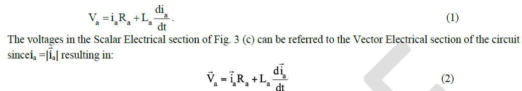
| The equivalent circuit of the three-phase stator with phase winding aa' energized is obtained by replacing the Magnetic Processes of Fig. 3(b) with current transformer CT and reluctance Ra. as shown in Fig. 3(c). The turns ratio of current transformer CT is 1:Na andRais the reluctance to flux ÃÂÃ⢠a. The complete equivalent circuit of the three-phase stator with phase winding aa' energized as shown in Fig. 3(c) consists of three sections: the Scalar Electrical section, the Vector Electrical section and the Vector Magnetic section. The current vectori aexists on the positive (+ ve) magnetic axis of winding aa' in the Vector Electrical section of the circuit, and the current transformer CT produces the magnetomotiveforce (mmf) Nai ain the Vector Magnetic section that drives the fluxÃÂÃ⢠athrough the magnetic circuit reluctanceRa. |
| The voltage equation in the Scalar Electrical section is given by: |
 |
| and producing the equivalent circuit of Fig. 4, with all voltages residing on the positive (+ ve) magnetic axis of winding aa'. Therefore the equivalent circuit of the three-phase stator with phase winding aa' energized has been represented by Vector Electrical and Vector Magnetic sections with current vector, voltage vectors and magnetic variables all existing on the positive (+ ve) magnetic axis of winding aa'. |
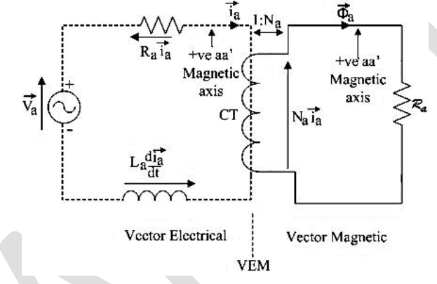 |
| Fig. 4. Equivalent Circuit of Three-Phase Stator with Winding aa' Energized with Vector Electrical and Vector Magnetic Sections |
IV. RESULTANT CURRENT VECTOR |
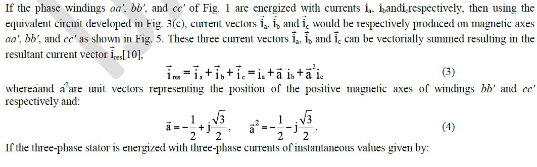 |
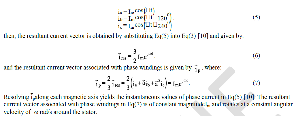 |
 |
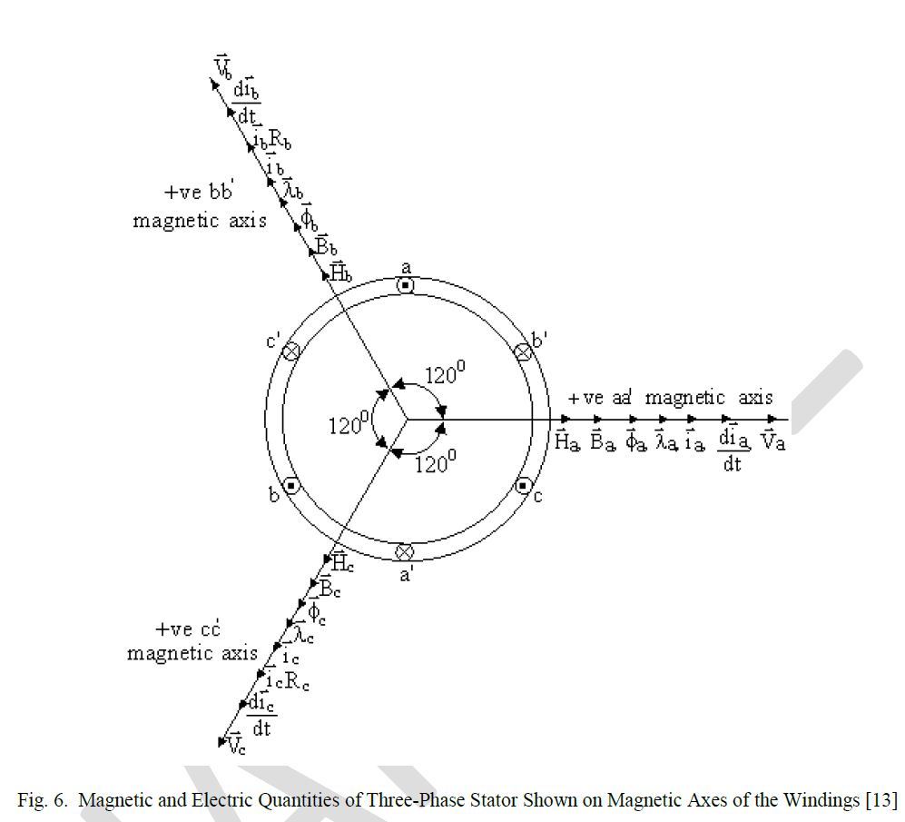
V.RESULTANT MAGNETIC AND ELECTRICAL VECTORS OF A THREE-PHASE STATOR |
| The application of the equivalent circuit of Fig. 3(c) to each phase winding of the three-phase, two-pole stator shown in Fig. 1, whose phase windings are displaced from each other by 1200, and energized by three-phase voltages, produces the magnetic and electrical quantities of each phase winding along the phase magnetic axis as shown in Fig. 6. |
| Each magnetic or electrical phase variable can now be summed vectorially to produce the resultant of that variable [10]. Hence, the resultant magnetic field intensity H res, flux densityB res, flux ÃÂÃ⢠res, flux linkage λ res, current vector i res, and supply voltage V resare given by the vector addition of their phase variables shown on the magnetic axes of Fig. 6. Applying the method utilized earlier to determine the resultant current vector associated with a phase winding to the above mentioned magnetic and electrical resultant vectors, the resultant magnetic and electrical vectors associated with a phase winding are given by: |
 |
 |
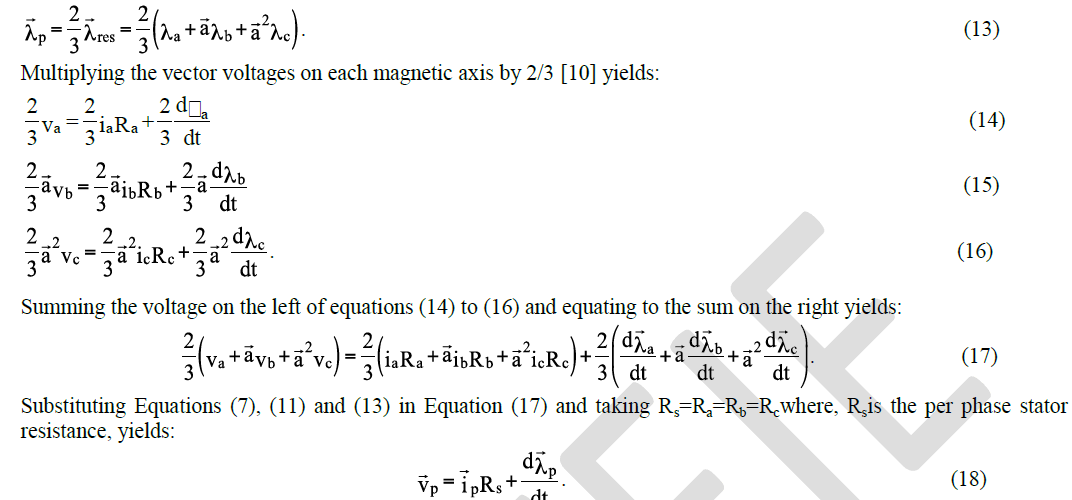 |
| Equation (18) presents a single voltage equation representing all three windings of the three-phase stator and the voltage equation of any phase winding is obtained by resolving the variables in this equation along the magnetic axis of the winding. |
VI. CONCLUSION |
| The development of an equivalent circuit for a phase winding of a three-phase stator consisting of scalar electrical, vector electrical and vector magnetic sections facilitated the referral of scalar electrical voltages to the vector electrical section of the equivalent circuit due to the equality of scalar and vector current magnitudes. This resulted in voltages and current coexisting with magnetic variables on the magnetic axis of the phase winding, thereby showing that electrical variables can be presented as vector quantities on the magnetic axis of the phase winding. The vector electrical section of the equivalent circuit connected the scalar electrical section to the vector magnetic section, resulting in a single circuit for analysis of the electromagnetic system. The energization of all three windings of the three-phase stator by three-phase voltages produced resultant current, voltage, and magnetic vectors associated with a phase winding and a single vector voltage equation for all three windings. The absence of this single equivalent electrical circuit of the electromagnetic system and the results derived from it has not inhibited growth in the area of transient analysis and modeling of electrical machines, however, its introduction reveals the background of the various phenomena occurring in the machine and shows the development of current and voltage vectors in the electromagnetic system. |
References |
|