International Journal of Advanced Research in Electrical, Electronics and Instrumentation Engineering
ISSN ONLINE(2278-8875) PRINT (2320-3765)
ISSN ONLINE(2278-8875) PRINT (2320-3765)
Sonal Naik1, Meenal Patil2, Shrikant Bhosale3, Anjali Shrivastav4
|
| Related article at Pubmed, Scholar Google |
Visit for more related articles at International Journal of Advanced Research in Electrical, Electronics and Instrumentation Engineering
Continuous innovations in automotive lighting technology pose the problem of how to assess new headlights systems. For car manufacturers, assessment is mostly relative. Given a headlights system to be tested how does it compare with another, maybe from a different supplier, in terms of features such as light intensity, voltage, current and power rating. This comparison is best performed dynamically, asking experts actually to drive along a certain testing track to write down later the visual impressions that they remember. Our paper includes the testing of physical parameters of headlights like current, intensity and voltage.
Keywords |
| LDR circuit; SMPS; interfacing PIC with LCD, keypad, DC motor to control movement of conveyor belt |
INTRODUCTION |
| The people are continuously raising their demand about automobile dependability and security with the development of the transport industry. The headlight is an important tool to protect the safe driving of vehicles. People have paid more and more attention for the performance testing of headlight. As such, their performance and features are being continuously enhanced by automotive component manufacturers. In addition to the external shape redesign, which is necessary to match the ever-changing aesthetic trends, new types of lamp and optical system have recently been introduced. Light sources can nowadays be halogen lights, high-intensity discharge (HID) (e.g. xenon) lights or lightemitting diodes. The traditional testing instrument of headlight performance has been unable to meet the requirements. It is a need to research a new testing system of headlight performance, which is advanced and practical in order to meet the need of the research, design and detection of the headlight. The main target of our paper is to design a testing system of headlight performance based on embedded system. The testing system is able to collect and process light image information of headlight in real time and show the results of intensity and axis offset. According to the overall needs of system designing, the design scheme based on embedded system was proposed and adopted and process light image information of headlight in real time and show the results of intensity and axis offset. In the same way, the headlights of a vehicle give a glimpse into its underlying character. While the form of most vehicles is captured through many components working in concert, the headlights are unique attributes that stand out. Many vehicles are identifiable solely by their headlights, which communicate the brand, vehicle class, and overall aesthetic. Engineers need to account for the headlight placement within the vehicle, ensuring that a proper spread of light will contact the road. There needs to be enough room to accommodate the grill and provide a joint between the hood and front bumper. The overall area of the headlight is an indication of the potential brightness of the headlight. |
II. LITERATURE SURVEY |
| Today PULSAR has captured the market. Lights are main attraction of it. So the customer needs that the lights should glow with proper intensity. Industries are not having any testing unit to measure intensity and calibrate it with the standards. So we are doing this innovative project to offer customized solution to suit application need. The design of a new car headlamp implies the conception of several prototypes and night tests according to the evolution of car styling. These prototypes and night tests are required for testing the performance validation of the lamp in driving conditions. |
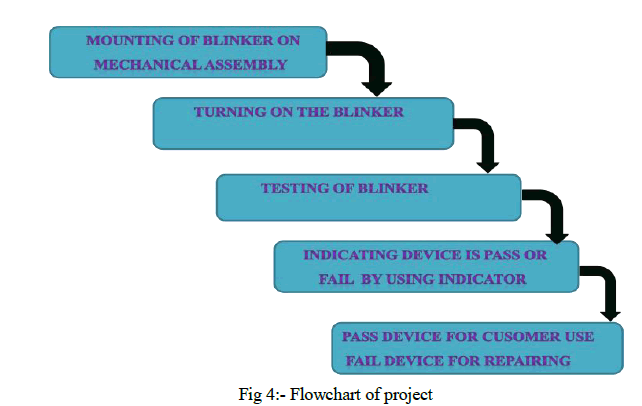
III. BLOCK DIAGRAM |
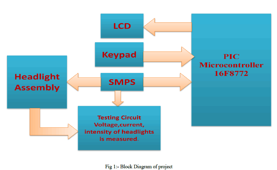 |
1) Headlight Assembly |
| Headlight assembly is a mechanical assembly on which blinker light of the bike is mounted for testing. Then voltage, current and intensities of bulbs of respective blinker are read using testing unit to which it is subjected. |
2) Testing Unit |
| It consists of LDR circuit used to measure mainly light intensity and voltage, current, power rating of the headlight under test. LDR circuit is followed by a buffer and then a sallen key filter used for filtering the fluctuations in measured values if any. |
3) SMPS Power Supply |
| Here we have used 1 SMPS that provides 12 V dc to the blinker which is a standard voltage. This 12V is converted to 5V using regulator and given to micro-controller for its operation. |
4) Keypad |
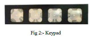 |
| System uses 4x1 keypad. Keypad is used by the user to enter into the different modes & also to change settings or set the tolerance values of different specifications. Keypad is the user interface to communicate with the Light Testing Unit. Keypad output is displayed on LCD through controller. |
5) Liquid Crystal Display (LCD) |
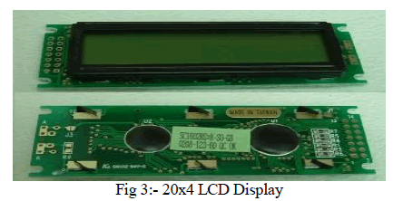 |
| a) 20x4 character LCD |
| b) LED backlight brightness |
| c) Voltage & current vary widely |
| d) Works on 5V supply |
| e) 5x8 dot matrix cursor |
| f) Built in controller |
| g) A 10KΩ pot is used for colour contrast control. |
6) PIC-Microcontroller (PIC 16f877A) |
| a) Address capability of up to 2 Mbytes. |
| b) 8, 12, 16 and20 bit Address modes. |
| c) Wide operating voltages ranging from 2V-5V |
| d) Four programmable external interrupts |
| e) 10-bit, upto16-channel Analog-to-Digital Converter module |
| f) Enhanced Flash program memory typical |
| f) Enhanced Flash program memory typical |
FORMULAE TO CALCULATE INTENSITY OF HEADLIGHTS IN LUX |
| The illuminance coming from the headlamp reaching a surface can be written according to the Lambert’s law as follows: |
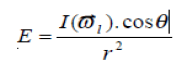 |
| with: |
| E: illuminance (Lux), |
| I (w): Intensity of the light source in direction l v (Candela), |
| ̩̉: the angle between the surface normale and l v, direction of incident light. |
| r: distance between source and surface point (m). |
| Therefore, the observed luminance is: |
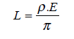 |
| With: |
| L: luminance (Candela/m²), |
| ρ: surface reflectance (constant for diffuse surfaces), |
| E: illuminance (Lux). |
IV. OVERVIEW |
 |
| 1) Our basic aim is to test the headlights and to check whether they meet requirements as per the standard values. |
| 2) Here we have considered blinkers which are bulbs that are to be tested that indicate pass and fail of the unit. |
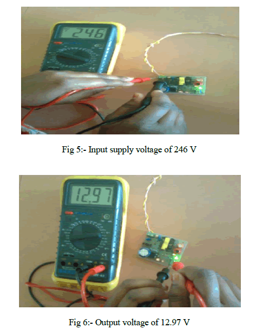
| 3) Here for testing purpose we have designed a 12 V SMPS whose input voltage as well the output voltage are been tested. This is shown below: |
 |
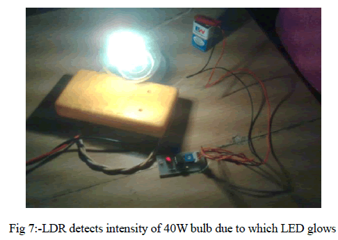
| 4) Now we have tested a 40W bulb over the LDR circuit where the LDR glows when the required intensity of light falls on the LDR.This is shown below: |
 |
| 5) Again keeping the distance constant we tested the glowing of LDR by bringing a LED into picture. The LDR doesn’t glow due to less intensity of LED as compared to the 40w bulb. |
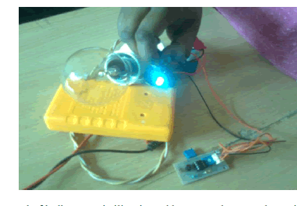 |
| Fig 8:- Keeping the distance constant, instead of bulb LED is illuminated but LDR does not detect its Intensity. Hence red LDR doesn’t glow. |
SIMULATION RESULTS |
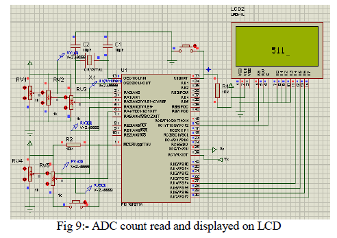
| Analog output of 1st LDR circuit of ADC channel 1 is read and displayed on LCD. PIC16f877A has a 10 bit ADC. Hence its maximum count will be from 0-1023. Value is read via a potentiometer. So when pot will be at 100% the value displayed on LCD will be 1023. Presently in the figure below, the pot is adjusted at 50% so the value displayed on LCD is half of 1023 i.e. 511. |
 |
V. CONCLUSION |
| Precision, boosting of productivity and Low cost is the basic need of industry and Automation has to be there to satisfy all this requirements. Also the Customization on site plays important role in improving the performance. Our project will definitely achieve all these requirements and help the industry to improve performance. |
| Presently we are reading the analog values of intensity, voltage and current using 3 channels of 10 bit ADC provided by PIC16f877A. Here they are converted to their respective digital values. Ideal values of measured parameters are stored in EEPROM of the micro-controller. Measured and ideal values are compared and depending on their results decision is taken whether the bulb is pass or fail. Result is displayed using bicolour led which will glow green for pass bulb and red for the fail one. Also the measured and ideal values of all 3 parameters are displayed using 20x4 LCD display. The designed testing unit is made more flexible using 4 key keypad. With the help of this one can manipulate the stored ideal values in EEPROM. Also the bulb assembly is made by placing 4 bulbs of different specifications on the conveyor belt which is controlled by a DC motor. |
| Out of the above mentioned work ADC and LCD display is already completed. Conveyor assembly and EEPROM work is under construction. |
References |
|