ISSN ONLINE(2278-8875) PRINT (2320-3765)
ISSN ONLINE(2278-8875) PRINT (2320-3765)
Pushpraj Singh Tanwar, Priyanka Shrivastava
|
| Related article at Pubmed, Scholar Google |
Visit for more related articles at International Journal of Advanced Research in Electrical, Electronics and Instrumentation Engineering
Very Large Scale Integration (VLSI) has made a dramatic impact on the growth of integrated circuit technology. It has not only reduced the size and the cost but also increased the complexity of the circuits. The positive improvements have resulted in significant performance/cost advantages in VLSI systems. There are, however, potential problems which may retard the effective use and growth of future VLSI technology. Among these is the problem of circuit testing, which becomes increasingly difficult as the scale of integration grows. Because of the high device counts and limited input/output access that characterize VLSI circuits, conventional testing approaches are often ineffective and insufficient for VLSI circuits. .The vital role of primitive polynomials for designing PN sequence generators. The standard LFSR (linear feedback shift register) used for pattern generation may give repetitive patterns. Which are in certain cases is not efficient for complete test coverage. The LFSR based on primitive polynomial generates maximum-length PRPG.Built-in self-test (BIST) is a commonly used design technique that allows a circuit to test itself. BIST has gained popularity as an effective solution over circuit test cost, test quality and test reuse problems. In this paper we are presenting an implementation of a tester using VHDL
Keywords |
| 1. LFSR (linear feedback shift register). 2. PRPG (Pseudo random pattern generator ) . 3. MISR (Multiple input signature register ) 4.Primitive polynomial 5. Galois field 6. BIST (Built in self test). |
INTRODUCTION |
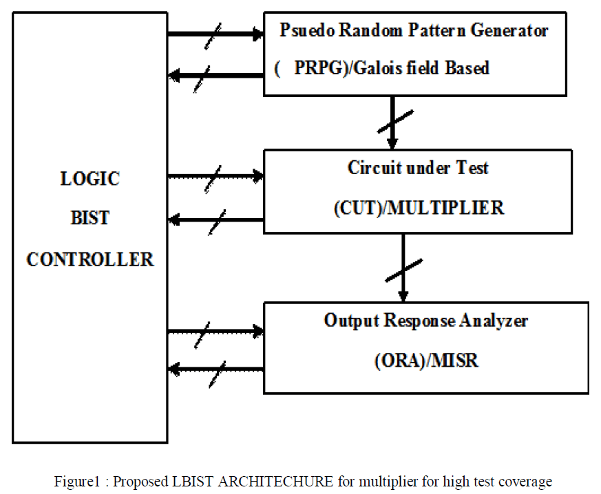
| Logic built-in self-test (L-BIST) is a design for testability (DFT) technique in which a portion of a circuit on a chip, board, or system is used to test the digital logic circuit itself. With logic BIST ,circuits that generate test patterns and analyze the output responses of the functional circuitry are embedded in the chip or elsewhere on the same board where the chip resides. As the complexity of circuits continues to increase, high fault coverage of several types of fault models becomes more difficult to achieve with traditional testing paradigms. Integrated circuits are presently tested using a number of structured design for testability (DFT) techniques. In this paper we use the BIST for multiplier technique. And its part LFSR, CUT(multiplier), MISR. In the test mode, a set of test patterns are applied to the circuit and responses are collected. The test responses are then compared with fault-free responses to determine if the CUT (multiplier) works properly. |
Literature Survey |
| In 1996, Charles R. Kime worked on the topic “MFBIST: A BIST Method For Random Pattern Resistant Circuits” A BIb'T architected that supports this technique, and a design tool (h4FBIST) that implements the technique are presented. The amount of hardware overhead 25 controlled by user-specified parameters and can meet tarrying design specifications. And the result of this paper has presented a BIST technique which combines bit-fixing and biased pseudorandom testing using multiple idler register segments. A design tool called MFBIST was also presented that implements the proposed BIST architecture. |
| In 2008, F., S. Chakravarty2, N. Devta-Prasanna2, S.M. Reddy1 and I. Pomeranz3 worked on the topic “An Enhanced Logic BIST Architecture for Online Testing” The objective of using logic BIST for online and periodic testing is to identify defects, like opens, resulting from the wear and tear of te circuit. We have shown that existing test sets have a low coverage for open defects located in scan flip-flops, even though such defects may affect functional operation. And the result is Using results obtained earlier for manufacturing tests, we discussed the shortcomings of current logic BIST structures in detecting open defects that are important in periodic field testing. Based on earlier results, we argued that if the stuck-open faults not detected by current logic BIST are left undetected, they may cause functional failures. |
| In 2010, “Tsu-Wei Tseng, Jin-Fu Li, Member, IEEE, and Chih-Chiang Hsu” worked on this topic. Built-in self-repair (BISR) technique has been widely used to repair embedded random access memories (RAMs). This paper presents a reconfigurable BISR (ReBISR) scheme for re-pairing RAMs with different sizes and redundancy organizations. An efficient redundancy analysis algorithm is proposed to allocate redundancies of defective RAMs. |
Proposed Work |
| In the previous works the test vector generators are based on normal polynomials so the test patterns may repetitive so the test coverage limits . some fault may not be recognized .but in our proposed work we design the primitive polynomial based on Galois field . For example 4 bit pattern generator should generates 2^4 – 1=(15) test vectors . But there may be possible that 2 or more test vectors generated may be same .because test vector generated randomly . hence effective no of test vectors are less . if our test vectors are less then our test coverage range shrinks. But in our proposed work our primitive polynomial based pattern generator generates non-repetitive test vectors. ie. If we use 4 bit PRPG it will generates 15 different test patterns. that means test patterns not repeats. so it will cover a large range of faults . |
 |
II.SYSTEM MODEL AND ASSUMPTIONS |
| (a) Galois filed based PRPG LFSR (pseudo random pattern generator ):- |
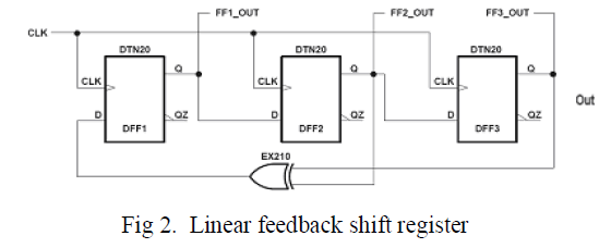
| For logic BIST applications, in-circuit PRPG constructed from linear feedback shift registers (LFSRs) are most commonly used to generate test patterns or test sequences for exhaustive testing, pseudo-random testing, and pseudoexhaustive testing. Exhaustive testing always guarantees 100% single-stuck and multiple-stuck fault coverage. This technique requires all possible 2n test patterns to be applied to an n-input combinational circuit under test (CUT), which can take toolong for combinational circuits where n is huge; therefore, pseudo-random testing is often used for generating a subset of the 2n test patterns and uses fault simulation to calculate the exact fault coverage. In some cases, this might become quite time consuming, if not infeasible. In order to eliminate the need for fault simulation while at the same time maintaining 100% single-stuck fault coverage, we can use pseudo-exhaustive testing to generate 2wor 2k−1 test patterns, where w<k<n, when each output of the n-input combinational CUT at most depends on w inputs. For testing delay faults, hazards must also be taken in to consideration. |
 |
(b) CUT (circuit under test) |
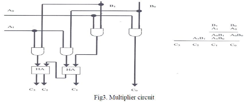
| Here the circuit under test is binary multiplier .Binary multiplication is similar in concept to decimal multiplication. The multiplicand is multiplied by each bit of the multiplier. We start from the least significant bit, as in decimal. Each such multiplication forms a partial product and successive multiplication is shifted one bit to the left. The final product is the sume of the partial products. Looking at a 2 bit by 2 bit multiplication of input values A1A0 by B1A0 would be done with the following circuit and give us the result of C3C2C1C0. When writing assembly language multiplication instructions, using the mul, you can see why the multiplier and multiplicand have to be the same size (n) and the product is twice as big ( 2n). |
 |
(c)MISR (Multiple input signature register):- |
| For BIST operations, it is impossible to store all output responses on-chip, on-board, or in-system to perform bit-by-bit comparison. An output response analysis technique must be employed such that output responses can be compacted into a signature and compared with a golden signature for the fault-free circuit either embedded on-chip or stored offchip. Compaction differs from compression in that compression is loss-less, while compaction is lossy. Compaction is a method for dramatically reducing the number of bits in the original circuit response during testing in which some information is lost. Compression is a method for reducing the number of bits in the original circuit response in which no information is lost, such that the original output sequence can be fully regenerated from the compressed sequence. |
 |
III. FAULT TESTING |
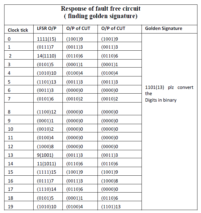
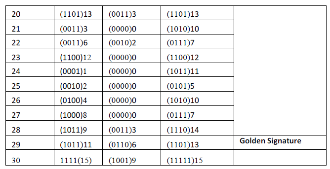
| The BIST pattern generation techniques described above mainly target structural faults, such as stuck-at faults and bridging faults, which can be detected with one pattern vectors. For delay faults requiring two-pattern vectors for testing, these methods do not provide adequate fault coverage. In this section, we discuss a few approaches that can be used for delay fault testing.Unlike structural fault testing that requires an exhaustive one-pattern set of 2ntest patterns, an exhaustive two-pattern set of 2n ( 2n −1)patterns is required to test delay faults in an n-input CUT exhaustively. This means that, for delay fault testing, one must use a test pattern generator (TPG) with 2n or more stages. A maximum length LFSR having 2n stages is called a double-length LFSRhas shown that when all even or odd stage outputs (called even taps or odd taps) of a 2n-stage double-length LFSR are connected to the n-input CUT, the LFSR can generate 22n −1 vectors to test the CUT exhaustively. While all delay faults are tested exhaustively, there is a potential problem that the test set could cause test invalidation due to hazards present in the design. Test invalidation or hazards can occur when more than one circuit inputs change values. More importantly, a circuit embedded with BIST circuitry can be easily tested after being integrated into a system. Periodic in-system self-test, even using test patterns with less than perfect fault coverage, can diagnose problems down to the level where the BIST circuitry is embedded. This allows system repair to become trivial and economical. Here we have table of finding golden signature. |
 |
 |
IV. VHDL IMPLEMENTATION |
| VHDL implementation of logic BIST ( built in self test) Architecture for multiplier circuit for high test coverage in vlsi chips using EDA tool Xilinx’s 8.2i, and simulation is done on Modelsim 6.3F. The RTL (register transfer level) of multiplier is shown is below. |
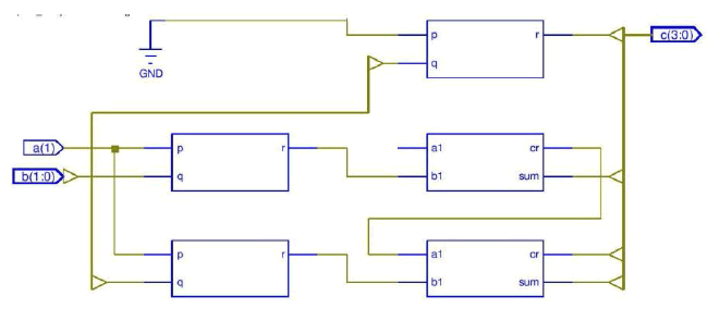 |
Fig5. RTL for faulty multiplier |
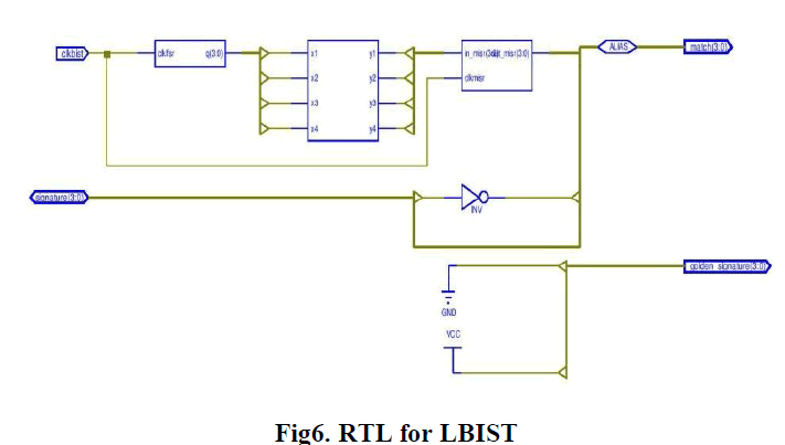
| Register-transfer level (RTL) is a design abstraction which models a synchronous digital circuit in terms of the flow of digital signals (data) between hardware registers, and the logical operations performed on those signals. The RTL of The RTL of logic BIST for multiplier is shown in figure and may be synthesize in Xilinx’s FPGA |
 |
V. SIMULATION RESULT AND DISCUSSION |
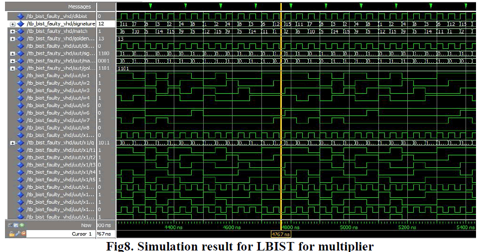
| The simulation is done on Modelsim and described below. In case faulty multiplier when the test vectors are supplied the product of the inputs gives fault output. which is clearly verified by the simulation result of faulty multiplier. i.e for a=0 b=3 the product is c= 2. Similarly for a=3 , b=1 the product is c=2. |
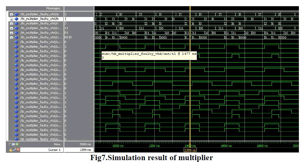 |
| When this faulty multiplier is comes under the test .The signature generator (1100) i.e 12 for it which mismatches from the golden signature(1101) i.e 13 already stored. |
 |
VI.CONCLUSION |
| An implementation of BIST logic using VHDL. LFSR is used as a pseudorandom sequence generator. Signature analysis is used to make verification of the circuit. Signature mismatch with the reference signature means that the circuit is faulty. However there is a small probability that the signature of a bad circuit will be the same as a good circuit. When longer sequence are used signature analysis gives high fault coverage. |
References |
|