ISSN ONLINE(2278-8875) PRINT (2320-3765)
ISSN ONLINE(2278-8875) PRINT (2320-3765)
| Kor Ashiwini N, Prof. P. H. Zope S.S.B.T’s College of Engineering & Tech. Bamhori, Jalgaon, India) |
| Related article at Pubmed, Scholar Google |
Visit for more related articles at International Journal of Advanced Research in Electrical, Electronics and Instrumentation Engineering
Machine Vision systems play an important role in vehicular instrumentation applications, such as traffic monitoring, traffic law reinforcement, driver assistance, and automatic vehicle guidance. These systems mounted in either out-door environments or in vehicles have often suffered from image instability. In-car applications, additional motion components are usually installed for disturbances such as the bumpy ride of the vehicle or the steering effect, and they will affect the image interpretation processes that required by the motion field detection in the image. Conventional road-vehicle systems depend almost entirely on human drivers. By exploiting emerging various technologies, road vehicle systems can be safer, more efficient, and more environment-friendly
Index Terms |
| Intelligent transportation system (ITS), digital image stabilization (DIS), video stabilization, advanced driver assistance system (ADAS) |
INTRODUCTION |
| Machine vision systems is key technology used in vehicular instrumentation to replace human driver visual capability. The worldwide deaths from injuries are caused due to 95% of all accidents this is the major cause to increase it [1], [2]. The vehicular instrumentation aims at reducing this stuff by developing various technologies for identifying different task of driving related risk factor and driver intentionality. The long-term goals of this include the identification of the factors involved in driving that impact traffic safety, the definition of sound principles for the design of automated vehicular safety technologies [1]. In this paper the various technologies such as intelligent transportation system, digital image stabilization technique, video stabilization technique, and advanced driver assistance system are describe to overcome traffic related problems. |
| While research on ADAS may integrate a number of different functions such as forward collision detection and lane departure tracking [3], little attention is devoted to the monitoring of event and factors that directly concern the driver of the vehicle. Since 95% of all accidents are caused by human error, it is important that these aspects of driving be a central part of i- ADAS [1], [4]. In ADAS, the driver is an active part of the feedback mechanisms allows for providing informational support and offer immediate application for enhancing safety [5]. In this paper, digital image stabilization (DIS) technique is describe to stably remove the unwanted shaking phenomena in the image sequences captured by in-car video cameras without the influence caused by moving object (front vehicles) in the image or intentional motion of the car, etc[6]. Digital image sequences acquired by in-car video cameras are usually affected by undesired motions produced by a bumpy ride or by steering. The unwanted positional fluctuations of the image sequence will affect the visual quality and impede the sub-sequent processes for various applications [6]. |
| The image stabilization systems can be classified into three major types: the electronic, the optical, and the digital V stabilizers. The electronic image stabilizer (EIS) stabilizes the image sequence by employing motion sensors to detect the camera movement for compensation. The optical image stabilizer (OIS) employs a prism assembly that moves opposite the shaking of camera for stabilization [7], [8]. Both EIS and OIS are hardware dependent, so the applications are restricted device built in online process. Intelligent Transportation Systems (ITS) is a tested route to mitigate traffic congestion problems. ITS can be broadly defined as the use of technology for improving transportation systems. The major objective of ITS is to evaluate, develop, analyses and integrate new technologies and concepts to achieve traffic efficiency, improve environmental quality, save energy, conserve time, and enhance safety and comfort for drivers, pedestrians, and other traffic groups [9], [10]. Stateof- art data acquisition and evaluation technology, communication networks, digital mapping, video monitoring, sensors and variable message signs are creating new trends in traffic management throughout the world. The synergy of data acquisition, analysis, evaluation, and information dissemination helps in developing an all-encompassing system of traffic organization that enables information sharing among the managers and users of traffic. |
RELATED LITERATURE |
| Many research groups provide brief descriptions of various technologies for vehicular instrumentation for reducing traffic related problem. In 1998, I. Masaki, gives the “Machine vision systems for intelligent transportation systems” and “Real-time vision for intelligent vehicles is given by D. Gavrila, U. Franke, C. Wohler, and S. Gorzig, both are vision system which uses various vision sensors such as camera, CCTV, camcorders Digital image stabilization is again one technology developed by Sheng-che Hu, Kang-fan, in March 2007. Multisensor instrumentation is also used to protect form accident and other causes. Advanced driver assistance system is developed in February 2012 by Steven S. Beauchemin, Michael a. Bauer and Taha Koswari, Jio Cho which provide better systems technology for overcoming the problem of traffic management, traffic injuries etc. |
INTELLIGENT TRANSPORTATION SYSTEM |
A. Types of ITS |
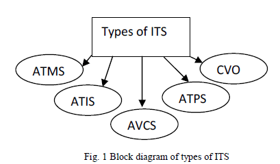
| Machine vision is a key technology used in any intelligent transportation system (ITS). . ITS research involves four major issues: increasing the capacity of highways, improving safety, reducing fuel consumption, and reducing pollution. ITS can use some intelligent control strategies, such as agent-based control concepts [11], [12], to manage the transportation and traffic problems. ITS applications typically have four sensors: acoustic, radar, laser, and machine vision. Although acoustic sensors are less expensive, their small detection range limits their application to backup warning and similar short distance systems [13]. |
 |
B. Component of ITS |
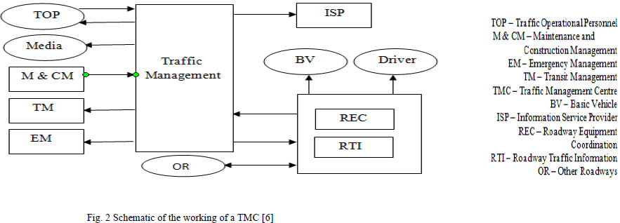
| A Traffic Management Centre (TMC) is the hub of transport administration, where data is collected, and analyzed and combined with other operational and control concepts to manage the complex transportation network. It is the focal point for communicating transportation-related information to the media and the motoring public, a place where agencies can coordinate their responses to transportation situations and conditions. Typically, several agencies share the administration of transport infrastructure, through a network of traffic operation centers. There is, often, a localized distribution of data and information and the centers adopt different criteria to achieve the goals of traffic management. This inter-dependent autonomy in operations and decision-making is essential because of the heterogeneity of demand and performance characteristics of interacting sub systems (see fig.2) [14]. The effective functioning of the TMC, and hence the efficiency of the ITS, depend critically on the following components: |
| 1) Automated data acquisition |
| 2) Fast data communication to traffic management centers |
| 3) Accurate analysis of the data at management center |
| 4) Reliable information to public/traveler |
 |
DIGITAL IMAGE STABILIZATION |
| Real-time digital image stabilization is used in some video cameras. This technique shifts the electronic image from frame to frame of video, enough to counteract the motion. It uses pixels outside the border of the visible frame to provide a buffer for the motion. This technique reduces distracting vibrations from videos or improves still image quality by allowing one to increase the exposure time without blurring the image. This technique does not affect the noise level of the image, except in the extreme borders when the image is extrapolated. |
A. Architecture of the dis and motion estimation |
| The system architecture of the proposed DIS technique is shown in Fig. 3, which includes two processing units: the motion estimation unit and the motion compensation unit. The motion estimation unit consists of three estimators: the LMVs, the refined motion vector (RMV), and the GMV estimators. The motion compensation unit consists of the CMV estimation and image compensation. The two incoming consecutive images frame (t − 1) and Frame (t) will be first divided into four regions. An LMV will be derived in each region by the RPM algorithm [18], [19]. The motion estimation unit also contains a reliability detection function that will generate an ill-conditioned motion vector for the irregular image conditions such as the lack of features or containing a large low-contrast area, etc. |
| The GMV estimation determines a GMV among LMVs, the RMV, and other preselected motion vectors through the adaptive background-based evaluation function. Finally, the CMV is generated according to the resultant GMV, and the image sequences will be compensated based on the CMV in the motion compensation unit. The rest of this section will focus on the details of the motion estimation unit of the proposed DIS technique [6]. |
 |
B. Motion Estimation |
| The motion estimation unit shown in Fig. 3 contains the LMV, RMV, and GMV estimators. The LMVs can be obtained from the correlation between two consecutive images by the RPM algorithm. The RMV can be obtained from LMVs by evaluating the corresponding confidence indices. RPM and Local Motion Estimation: It has been demonstrated that a local approach using a regional matching process is more robust and stable than a direct global matching process [21], [6]. That means using the LMVs estimated by the divided regions to determine the GMV is more robust and stable than a direct approach. |
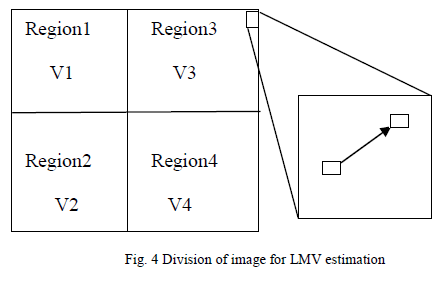 |
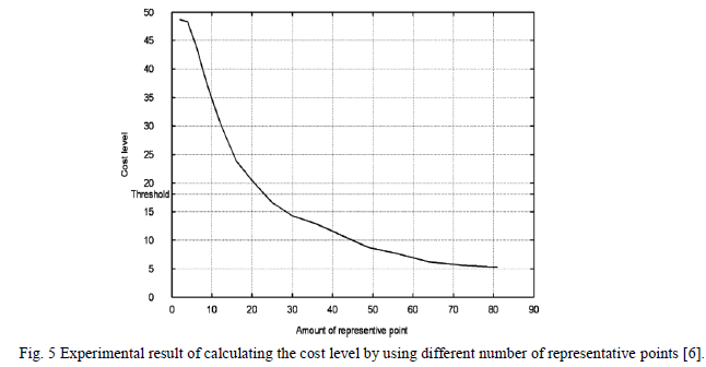
| So, to divide the image such that the horizontal and vertical components have the same partitions, it should be divided into n2 regions. More divided regions will increase the computational cost to estimate the LMV for each region. Therefore, we only divide the image into four regions as shown in Fig.4 for the RPM method, and it can cover various situations in the in-car DIS applications by combining the proposed inverse triangle method and the adaptive background evaluation model [6]. Each region is further divided into 30 sub-regions (with each side of 5 rows × 6 columns), and the central pixel of each sub-region is selected as the representative point to represent the pattern of this sub-region. This layout is based on the size of images captured by the regular imaging devices such as 640 × 480 or 320 × 240[6]. In order to make the representative points equally distributed in spatial, the ratio of row and column should be maintained by as close to 0.75 as possible. Fig. 5 shows the experimental result of calculating the cost level by using different number of representative points. The higher cost level indicates the lower reliability, and the threshold is set as 18. It is the averaged testing result for four experimental video sequences VS#1–4 used in Section IV. It can be found that if the number of the representative points is larger than 30, the cost level will go down to the threshold and almost all the motion vectors calculated by the RPM method are reliable. In other words, in this case, the cost level will be good enough as the lower cost level indicates high reliability. In order to keep low computation time complexity, 30 representative points are use in our system [6]. Then the correlation calculation of RPM with respect to representative point (Xr, Yr) is performed as |
 |
 |
ADVANCED DRIVER ASSISTANCE SYSTEM |
| Today ADAS are commonly used in all kinds of vehicles. The aim of ADAS is to Provide assistance to the driver, by informing them about the car, the road, or any potential hazard, or by providing an active assistance, such as emergency braking. Two European projects comunicar [15] and stardust [16], both review the state-of-the-art. The ADAS can be grouped into five categories, lateral control systems, longitudinal control systems, reversing or parking aids, vision enhancements systems, and intelligent speed adaptation [17]. |
A. Layers of vehicular instrumentation |
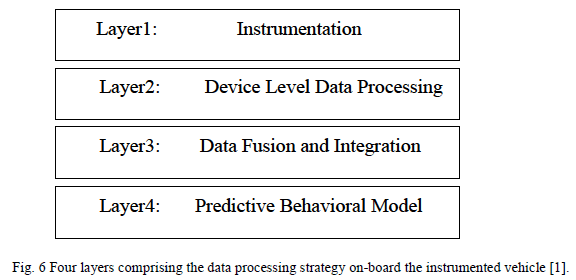
| The next generation of i-ADAS will require extensive data fusion and analysis processes owing to an ever increasing amount of available vehicular information. In this context, a layered approach is best suited for real-time processing. In particular, such an approach enables bringing real-time data from sensors to a common level of compatibility and abstraction which significantly facilitates fusion and analysis processes [1]. The proposed computational model consists of four layers, with increasing of data abstraction (see Fig. 6). The innermost layer consists of the hardware and software required to capture vehicle odometry, sequences from visual sensors, and driver behavioral data. The second layer pertains to hardware synchronization, calibration, real-time data gathering, and vision detection processes. The third layer is where the data is transformed and fused into a single 4-D space (x, y, z, t). The last layer makes use of the fused data to compare driver behavioral data with models of behavior that are appropriate given current odometry and traffic conditions. While we proceed to describe the four layers, it is to be noted that this contribution specifically Addresses the instrumentation (layers one and two) and its performance evaluation [1]. |
 |
| Range resolution of stereo system |
| The dual stereo systems constitute an essential component of the instrumented vehicle and for this reason, their performance (related to raw 3-D depth data) are crucially important. Consider the problem of range resolution, which is inversely related to object distance. The relationship governing range resolution is given by |
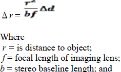 |
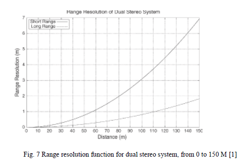
| d = pixel size divided by the Interpolation factor of the epipolar scan-line algorithm (for sub pixel precision 2-D matching) [1]. The range resolutions for our dual stereo systems constitute a reliable indication of the error levels contained in the depth data, provided that calibration is accurate and that the depth measurements do not stem from incorrect 2-D matches (due to occlusion, spatial aliasing, image noise, or related problems). Much dense stereo vision algorithms have been comparatively evaluated including that of OpenCV, which we use) with image sequences for which true depth is available in terms of incorrect match density and resilience to noise [20]. The short-range stereo system has a baseline of length b = 357 mm, a smallest detectable 2-D disparity of (1/16) of a pixel, a focal length of f = 12.5 mm, and a physical pixel square size of 4.40 μm. The long-range stereo system differs only in its baseline (b = 678 mm) and focal length (f = 25.0 mm). Fig. 7 displays the range resolution functions for both stereo systems. As expected, the range resolution of the long- range stereo pair surpasses that of the short range, due to an extended baseline and a longer focal length of the lens [1]. |
 |
| Computed the average match density of both the long and short-range stereo systems using instrumented sequences produced with the vehicle on public roads. Where different values of the minimum disparity were used. The short-range stereo system performs better in terms of density, due to several factors, including the reported fact that operational vibrations introduce more noise in long-range systems [1]. |
CONCLUSION |
| The development and implementation of advanced technologies is important to the successful management and operation of ITS in India. These technologies include electronic equipments such as sensors, detectors and communication devices and application of global navigation satellite system (GNSS). The DIS describes the remarkable performance in both quantitative and qualitative (human vision) evaluations compared to the available conditions related to the traffic problem. It can be implemented as software and hardware solutions for both online and offline video stabilization applications. The data processing strategy of the vehicle instrumentation within a layered approach in which data abstraction increases with the number of layers. |
ACKNOWLEDGMENT |
| The satisfaction that accompanies that the successful completion of any task would be incomplete without the mention of people whose never-ending cooperation made it possible, whose constant guidance and encouragement crown all efforts with success. I am grateful to our project guide Prof. P. H. Zope for the guidance, inspiration and constructive suggestions that helpful us in the preparation of this seminar. |
| Last but not the least, I am thankful to all my friends and well-wishers to whom I am indebted for their constant help, encouragement and without whom this seminar would not have been a success. |
References |
|