International Journal of Advanced Research in Electrical, Electronics and Instrumentation Engineering
ISSN ONLINE(2278-8875) PRINT (2320-3765)
ISSN ONLINE(2278-8875) PRINT (2320-3765)
Neena Mani1, Ammu Catherine Treesa2, Anju Sivadas3, Celus Sheena Francis4, Neethu M.T.5
|
| Related article at Pubmed, Scholar Google |
Visit for more related articles at International Journal of Advanced Research in Electrical, Electronics and Instrumentation Engineering
Our project focuses on a surveillance system that can be provided in case of a hazard when communication has been cut down. An unmanned aerial vehicle preferably a quad rotor helicopter sent to the hazard spot showing a live video telecast at the operating side can give information about the hazard substantially. The system consists of mainly a webcam for live video tracking and also different sensors for knowing the condition of vehicle location. The location of the vehicle is given with the help of a GPS module incorporated on the system. The controller used here for different communication and control purposes is PIC16F877A, this PIC being easily available and latest in the market. The wireless communication between the system, including the dummy vehicle, and the user (PC) is by Zigbee wireless communication system. Presently the system built by us lacks the size compatibility to be mounted on an actual quad copter. By reducing the size by integration we can actually mount it on a quad copter. By various additions on the system it can be actually used for disaster management and defence purposes.
Keywords |
| GPS, ZigBee, microcontroller, Relay board, IR Sensor |
INTRODUCTION |
| Consider the case of a disaster occurred in an area. The area then becomes remote due to the blockage and destruction of the communication lines. The rescue operations often cannot be done accurately without knowing the exact location of the disaster. In such cases video surveillance from a large altitude is required. This is possible with the help of an unmanned aerial vehicle (UAV) which is not too large with a surveillance camera fitted on to it. The control of the vehicle and camera are in hands of the rescue operators. Unmanned aerial vehicle had developed for many years with quad rotor vertical takeoff and landing unmanned aerial vehicle developing fastest. Up to now, the quad rotor unmanned aerial vehicle has already become one of the unmanned aerial vehicles that can fly stably. The inclusion of defence mechanism makes the unmanned aerial robot not an ordinary UAV any longer, but an intelligent robot that can fly. A video surveillance system (short VSS) offers the possibility of visual surveillance while the observer is not directly on site. Surveillance may be performed not only directly but may also be stored, evaluated and repeated as often as necessary. Video technology may be used among others for control and regulation purposes |
II.RELATED WORKS |
| A visual tracking system on an unmanned aerial vehicle is a similar work.The vehicle control and video output tuning are in the user’s hands. Studying some references we got an idea that a quad rotor helicopter (quadcopter) can be made into an intelligent aerial vehicle. With the aid of necessary communication set ups and a CCD camera we can get a visual tracking system. The system has two parts, namely, the vehicle and the controller. The communication being ZigBee as it is uninterrupted even when communication lines like telephone lines are cut off. |
| (“Visual track system applied in Quadrotor aerial Robot”, 2012 Third International Conference on digital Manufacture and Automation, 2012 IEEE,Jie-Tong Zou) |
| We decided to make an equivalent vehicle since quadcopter construction is difficult and flight is nearly uncertain if any such is made. The vehicle needed a base and wheels attached to a base. Vehicle base held the PCB and all other modules which came along. The datasheets on different ICs were searched for. The controller being used is PIC16F877A due to several advantages it had like being self programmable, affordable etc. |
| (Microchip Technology, “PIC 16F87XA Datasheet”, 2003) |
III.SYSTEM OVERVIEW |
| Our project basically consists of three stages. |
| 1. Construction of moving vehicle |
| 2. Design and construction of onboard electronic equipments |
| The parameters that are monitored |
| 1. Position |
| 2. Fire |
| 3. Temperature |
| Position is obtained from the GPS module. Temperature is measured by using temperature sensor. All this information are processed by the PIC16F78 controller and send to the base station using Zigbee transceiver zigbee transceiver at the base station processes the incoming data and displays it on the computer screen. Video tracking is performed by means of a wireless webcam.. |
IV.HARDWARE DETAILS |
| Transmitter section consist of PIC16F877A microcontroller, GPS module, Temperature sensor, IR fire sensor, Zigbee module, Webcam, LCD display. Receiver section consists of Zigbee module and computer. |
(A) GPS module: |
| The Global Positioning System (GPS) is a space-based satellite navigation system that provides location and time information in all weather conditions, anywhere on or near the Earth where there is an unobstructed line of sight to four or more GPS satellites. The system provides critical capabilities to military, civil and commercial users around the world. It is maintained by the United States government and is freely accessible to anyone with a GPS receiver.A GPS receiver calculates its position by precisely timing the signals sent by GPS satellite high above the Earth. Each satellite continually transmits messages that include the time the message was transmitted and satellite position at time of message transmission. |
(B) Relay Control Unit: |
| The RCU consisting of a high power relay is a vital part in the system. It provides the useful functionality of switching the power ON/OFF to the user based on the signal send to it from the controller corresponding to the status of bill payment. A relay is an electrically controllable switch widely used in industrial controls, automobiles and appliances. The relay allows the isolation of two separate sections of a system with two different voltage sources i.e., a small amount of voltage/current on one side can handle a large amount of voltage/current on the other side but there is no chance that these two voltages mix up. When current flows through the relay coil, a magnetic field are created around the coil i.e., the coil is energized. This causes the armature to be attracted to the coil. The armature’s contact acts like a switch and closes or opens the circuit. When the coil is not energized, a spring pulls the armature to its normal state of open or closed. There are all types of relays for all kinds of applications. When a command is received by the microcontroller to disconnect or reconnect the load then by using this relay the operation is performed. |
(C) PIC 16F877A Microcontroller: |
| This is a CMOS FLASH based 8 bit, 40 pin microcontroller. It has five I/O ports. The PIC16F877A features 256 bytes of EEPROM data memory, self programming, 2 Comparators, 8 channels of 10-bit Analog-to-Digital (A/D) converter, 2 capture/compare/PWM functions, the synchronous serial port can be configured as either 3-wire Serial Peripheral Interface or the 2-wire Inter-Integrated Circuit bus and a Universal Asynchronous Receiver Transmitter (USART). It works at an operating voltage range of 2V to 5V. The microcontroller calculates the number of units consumed based on the signal received from the IR sensor. The microcontroller has a USART module which provides a cost effective, simple and reliable communication between one controller to another or between a controller and a PC. It also sends appropriate signal to the relay to connect or disconnect the load. |
(D) Wireless webcam: |
| A webcam is a video camera that feeds or streams its image in real time to or through a computer or computer network. When "captured" by the computer, the video stream may be saved, viewed or sent on to other networks via systems such as the internet, and email as an attachment. When sent to a remote location, the video stream may be saved, viewed or on sent there. Software is available to allow PC-connected cameras to watch for movement and sound, recording both when they are detected. These recordings can then be saved to the computer, e-mailed, or uploaded to the Internet. Webcams can be used to take video clips and still pictures. |
(E) Liquid Crystal Display (LCD): |
| A 16 x 2 alphanumeric LCD is used which displays the number of units of energy consumed. To display the information on LCD, the microcontroller has to send its ASCII value to the data pins of the LCD. |
(F) Zigbee Transceiver: |
| The Zigbee Transceiver Module provides bi-directional communication between two-way enabled RTI remote controls and control processors utilizing Zigbee wireless communication. Capable of being hard-wired directly to a control processor or be used as a wireless repeater device to create an ultra-reliable, self-healing “mesh” network. |
| Utilizing the latest in wireless technology, the Transceiver Module is capable of more than just receiving signals - it can transmit signals as well. This creates a bi-directional communication link between Zigbee enabled RTI control processors and handheld remote controls. Feedback, such as song meta-data or volume level from supported devices can now be viewed on the remote control. |
(G) Temperature sensor |
| In our project we are using temperature sensor LM35 to measure the atmospheric temperature. The 10 bit analog to digital converter in PIC16F78 microcontroller converts the analog output from the sensor to corresponding digital signal. The controller continuously monitors the atmospheric temperature and sends it to the base station. |
(H) IR sensor: |
| The IR Sensor-Single is a general purpose proximity sensor. Here we use it for collision detection. The module consists of an IR emitter and IR receiver pair. The high precision IR receiver always detects an IR signal. The module consists of 358 comparators IC. The output of sensor is high whenever it receives IR frequency and low otherwise. The onboard LED indicator helps user to check status of the sensor without using any additional hardware. The power consumption of this module is low. It gives a digital output. |
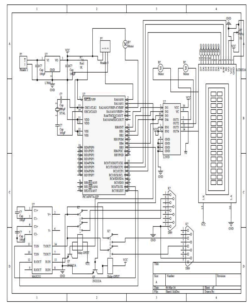 |
| The above figure shows the various connections of the components to the controller |
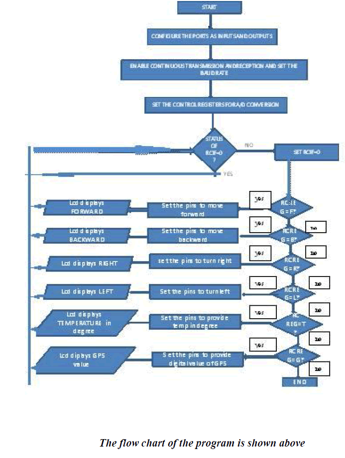
V. SOFTWARE ARCHITECTURE |
| The flowchart of the program code has been shown as follows. As per the instructions given by the controller the vehicle moves. |
 |
VI.RESULT AND CONCLUSION |
| We have designed and set up an unmanned vehicle which can be controlled by an individual at a distance with a simple PC or laptop. The Zigbee wireless communication used here has a range of about 100m. There is a live video tracking facility along with temperature sensing, a fire extinguisher and Global Positioning System (GPS). The vehicle control is done by the user using simple English letters such as F, S, R etc. This is mainly used for visual surveillance during a disaster or for wildlife photography. |
| The surveillance system we have developed is a road based or floor-based system. The system when mounted on a moving aerial vehicle it is more use and better video tracking. A quad rotor helicopter or the so called quadcopter is one such unmanned aerial vehicle which can be used. Our system is not light weight and cannot be mounted on a quadcopter since the vehicle may not lift due to weight. Reducing component size and small integrations helps to overcome this problem. |
References |
|