ISSN ONLINE(2278-8875) PRINT (2320-3765)
ISSN ONLINE(2278-8875) PRINT (2320-3765)
| K.Subbulakshmi Assistant Professor, Department of ECE, Bharath University, Chennai-600073, India |
| Related article at Pubmed, Scholar Google |
Visit for more related articles at International Journal of Advanced Research in Electrical, Electronics and Instrumentation Engineering
It is known that the application of PID controller span from small industry to high technology industry. Due to PID controllers' widespread use in industry, tuning procedures for them are always a topic of interest. In this dissertation, it is proposed that the controller be tuned using the Genetic Algorithm technique. Using genetic algorithms to perform the tuning of the controller will result in the optimum controller being evaluated for the system every time. For this study, the model selected is a fault tolerant system. The PID controller of the model will be designed using the classical method and the results analyzed. The same model will be redesigned using the GA method. The results of both designs will be compared, analyzed and conclusion will be drawn out of the simulation made. Then the optimized Proportional-Integral- Derivative (PID)Controller is evolved using Field Programmable Gate Array (FPGA)technology. The algorithm is implemented usingDistributed Arithmetic (DA)-based scheme where a Look-Up-Table (LUT) mechanism inside the FPGA is utilized. Twonovel DA-based PID controllers have been proposed for FPGAimplementation. The implementation results show that, the twoDA methods require 13% and 4% of logic devices, respectively,compared to the design using multipliers. Furthermore, thepower consumption is reduced by about 40%. A design whichis efficient in terms of power consumption and chip areawhile having adequate speed means that the FPGA chip canbe used to accommodate more controllers with low powerconsumption, resulting in a cost reduction of the controllerhardware.
Keywords |
| Genetic Algorithm, FPGA design, distributed arithmetic, power optimization, PID controller. |
INTRODUCTION |
| The interest in the use of Evolutionary Computation techniques, such as Evolvable Hardware [1][2][3], Genetic Algorithms [4] and Genetic Programming [5], in the design of intelligent and flexible controllers has shown a considerable increase lately. In the last decades, PID controllers have been successfully applied to many different problems in the control field and have achieved valuable results [6]. Due to their widespread use in industry, tuning procedures for PID controllers are always a topic of interest [6]. Traditionally, tuning procedures for them are based on designer’s experience and intuition or make use of the classical Ziegler-Nichols method whenever it is possible. An Evolvable PID controller consists of a PID controller hardware whose gains can be set by Evolutionary Computation techniques. The main objective of this work is to investigate the use of Genetic Algorithm in the tuning of PID controllers. Genetic algorithms are inspired in natural immunological mechanisms. This technique is basically a procedure of adaptive and parallel search [7][8]. The genetic algorithm searches for the controller gains Kp(proportional), Ki (integral) and Kd(derivative or differential) so that specifications for the closed-loop step response are met. In the following section basic concepts and modeling of the Evolvable PID controller are presented. |
II. EVOLVABLE PID CONTROLLER |
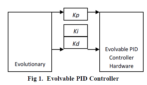 |
| An Evolvable PID Controller (Figure 1) consists of a PID controller hardware whose gains Kp, Ki and Kdcan be set by Evolutionary Computation techniques. exist. In evolvable PID controller an evolutionary algorithm sets the gains to the PID controller hardware so that design requirements are well satisfied. An evolutionary algorithm namely the genetic algorithm, is used for tuning the controller. By using this procedure, designers need only specify the desired closed loop response. This evolutionary nature entitles the controller to self-adaptations, which are important in applications where controllers need to operate for long periods in harsh environments. The block diagram of the evolvable PID controller is shown above.The implementation of the tuning procedure of a PID controller through the GA starts with initial population with three real numbers that characterize the individual to be evaluated and that correspond to the three gains (Kp, Ki and Kd) to be adjusted in order to achieve a satisfactory behavior. Since the objective is to minimize the error between the set point (desired output) and the plant output (actual output), the affinity function has been defined as: |
 |
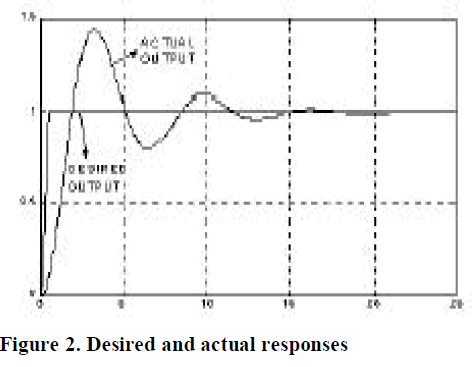
| The genetic algorithm searches for the best individual (controller) maximizing the affinity (between 0 and 1). Desired and actual responses for a given system are shown in Figure 2. |
 |
III.OPTIMIZING OF THE DESIGNED PID CONTROLLER |
| The optimizing method used for the designed PID controller is the .steepest gradient descent method. In this method, we will derived the transfer function of the controller as |
 |
| The minimizing of the error function of the chosen problem can be achieved if the suitable values of q can be determined. These three combinations of potential values form a three dimension space. The error function will form some contour within the space. This contour has maxima, minima and gradients which result in a continuous surface. The idea of this optimization method is reach the minima by the shortest path. In order to achieve this shortest path, moving down the steepest gradient will lead to reaching the minima the soonest. When the gradient changes from point to point, to ensure that the steepest path is still being used, it is significant to choose a new direction and make changes accordingly. Hence the minimization of the error function is achieved by analyzing the function of the function itself. |
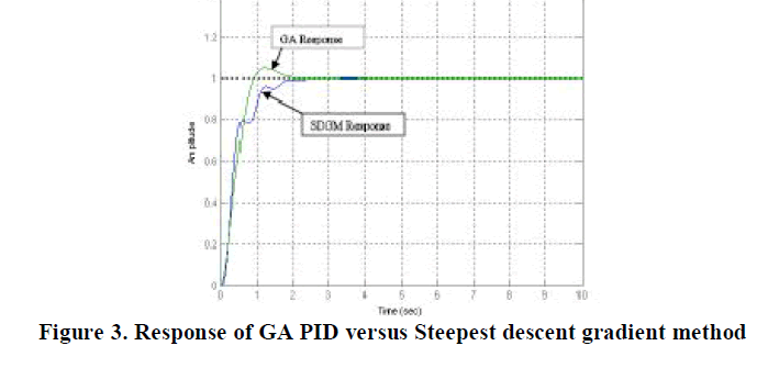 |
| The population size of 90 and above were tried and the program has not shown any sign of improvement in the optimization. Hence a decision was made to stick to the population size of 80 and analyzed it against the Steepest Descent Gradient Method PID optimization. Proceeding with the higher population size will take up a lot of computer memory space. Since the Genetic Algorithm designed PID with population size of 80 seems to have the best response as compared to the others responses. Now how does the GA designed PID stands against the Steepest Descent Gradient Method PID? The above plot shows that the GA designed PID performed better than the Steepest Descent Gradient Method (SDGM). |
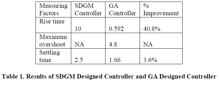 |
| Results Of SDGM Designed Controller and GA Designed Controller is tabulated below. From the above table, we can see that the GA designed controller has a significant improvement over the SDGM designed controller. On average the percentage improvement of GA controller against SDGM controller range from 30 % to GA Response SDGM Response 40 % with the exception of the measurement on overshoot. In the SDGM controller, it out performed the GA designed controller. However the setback is that it is inferior when it is compared to the rise time and the settling time. This is where GA excels. Finally the improvement has implication on the efficiency of the system under study. |
IV.PID CONTROLLER IMPLEMENTATION |
| The application of a PID controller is a fault tolerant system. As we know kp, Ki and kd are the control parameters. The simplest form of the PID control algorithm is given by |
 |
| From a practical point of view, implementation of the above algorithm has certain limitations [4]. Firstly, actuator saturation can cause integrator wind-up, leading to a sluggish transient response. Secondly, the pure differentiation term amplifies noise, leading to a deterioration of the control command. Finally, the differentiation term acts on the error signal, taking the derivative of the command signal as well. This procedure can lead to spikes in the command signal when, for example, a user changes the set-point abruptly. In the following section [10], a modified PID control algorithm that overcomes the above problems is given in the Laplace domain by |
 |
| where K, b, Ti, Td, and N are controller parameters, and U(s), Uc(s), and Y (s) denote the Laplace transforms of u, uc, and y, respectively. In order to implement the control algorithm using digital technology, equation (2) has to be Discretized. Denoting the sampling period by T, and using backward differences to discretize the derivative term and forward differences for the integral term, one has |
| where k denotes the k-th sampling instant. Now let us see the two types of implementations namely Distributed Arithmetic I and II |
A. Direct DA Implementation (DA-I) |
| Let us consider the controller terms given in (4). Assuming that u(kT), u((k − 1)T), y(kT), and y((k − 1)T) are m-bit numbers and [j] represents the jth bit of the numbers, we have |
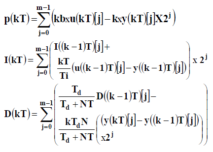 |
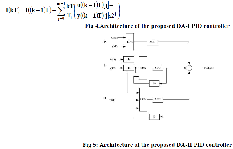
| K, b, Ti, Td, N are controller parameters, and T is the sampling period. The results of the above expressions can be precomputed and stored in three LUTs, Based on the above equations, the direct DA implementation of the PID controller, namely, DA-I, is shown in Figure 4. It consists of four delay blocks, three LUTs, three ACCs, and two adders. The delay blocks 1 and 2 are used to obtain u((k−1)T) and y((k−1)T), respectively. The delay blocks 3 and 4 are used to generate the terms I((k − 1)T and D((k − 1)T), respectively. Using the three LUTs and the corresponding shift-add accumulators (ACCs), the P(kT), I(kT), and D(kT) terms can be obtained in m clock cycles. The main advantage of the DA expression lies in its capability to compute the PID function utilizing the LUT rich FPGA. Based on the above equations, the direct DA implementation of the PID controller, namely, DA-I, is shown in implemented. |
B. Direct DA II Implementation (DA-II) |
| In order to improve the efficiency of the design, we apply a pipeline scheme to utilize the direct DA implementation. For the I(kT) term, |
 |
 |
 |
| For the D(kT) term we revise the predefined equation as follows: |
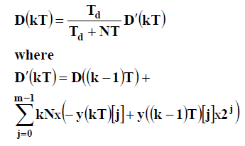 |
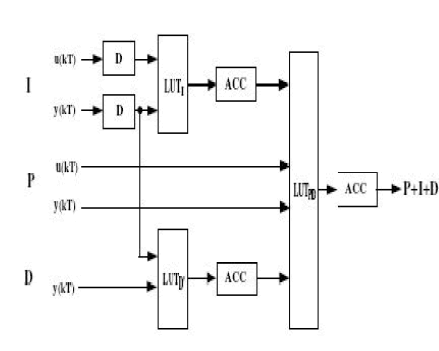
| The LUT and the corresponding ACC LUT and the corresponding ACC will generate the PIDoutput in m clock cycles, in the second pipeline stage. Thistwo-stage implementation of the DA-based PID controller, namely, DA-II, is shown in Figure 3. It requires three LUTs, three ACCs and two delay blocks while DA-I requires two more adders and two more delay blocks. Thus, the hardware resources required by DA-II are less than those of DA-I. DA-II needs two stages to accomplish one PID calculation in a pipeline. The first stage consists of two LUTs and two CCs to calculate I(kT) and D_(kT), respectively. |
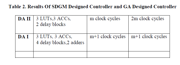
| The second stage consists of one LUT and one ACC to calculate the summation of the PID function using the results of I(kT) and D_(kT) available in the first stage. These stages are pipelined so that when the second stage is performing the first calculation, the first stage is performing the next calculation. Thus, the throughput (speed) is only m clock cycles. The two stages, each requiring m clock cycles, introduce a latency of 2m clock cycles. The performance, in terms of complexity and speed, of the proposed designs, and the multiplier-based design are listed in Table 2. Compared to the multiplier-based PID controller, the two DA-based designs, DA-I and DA-II, utilize the memory rich characteristics of the FPGA. The proposed design (DA-II) requires less adders/sub tractors and less delay blocks as compared to the direct DA implementation, i.e., DA-I. The speed (throughput) of DA-II design is a little bit higher than that of DA-I, but the latency is more. Since the latency only occurs once during the power up, it is not of much concern in our control system consideration. Thus, the DA-II design has improved characteristics compared to DA-I and is the most preferred design in the control system amongst the three designs.. |
V.SIMULATION RESULT |
 |
VI. CONCLUSIONS |
| In conclusion the responses had showed to us that the designed PID with GA has much faster response than using the classical method. The classical method is good for giving us as the starting point of what are the PID values and finally genetic algorithm gives the optimum solution. And also two novel DA-based PID controllers have been proposed for FPGA implementation. By using the DA based LUT scheme, the memory inside FPGA has been utilized to provide efficient design for PID controllers. The, FPGA implementation results show that, the two DA designs requires only 13% and 4% of logic devices, respectivelycompared to the design using multipliers. Furtherthe power consumption is reduced by about 40%, thus giving an efficient implementation scheme. |
References |
|