ISSN ONLINE(2278-8875) PRINT (2320-3765)
ISSN ONLINE(2278-8875) PRINT (2320-3765)
Ninu Joy1, Rajan P Thomas2, Benny Cherian3
|
| Related article at Pubmed, Scholar Google |
Visit for more related articles at International Journal of Advanced Research in Electrical, Electronics and Instrumentation Engineering
This paper deals with controlling of both voltage and frequency for standalone wind power generating systems. The proposed controller has bidirectional active and reactive power flow capability along with battery energy storage system by which it controls the system voltage and frequency with variation of consumer loads and speed of wind. The proposed system is modelled and simulated in MATLAB using simulink .The proposed controller has additional capability of harmonic elimination and load balancing and hence power quality can be improved.
Keywords |
| Battery energy storage system, isolated asynchronous generator, voltage and frequency controller, wind energy conversion system. |
INTRODUCTION |
| Some of the areas are remote so that it is very difficult for those areas to access main power grid. So it is necessary to meet the demand of remote areas. Wind is the most prominent source of energy available. We can easily exploit by using asynchronous generator .Squirrel cage induction are low cost, robust and simple in its construction. Wind speed and load are varying, so in order to maintain voltage and frequency here employing a voltage and frequency controller for standalone wind power generating systems. |
| The proposed voltage and frequency controller is having bidirectional active and reactive power flow capability by which it controls the system voltage and frequency with variation of consumer loads and wind .It has additional capability of harmonic elimination and load balancing .The performance is demonstrated using standard MATLAB software. |
| This paper is organised as follows: Section I gives the importance of wind generating system and a controller. Section II is helpful to understand the configuration of an isolated wind energy system. Section III explains the control strategy .Section IV deals with modelling of control scheme. .Section V deals with the analysis and design of controller. Section VI deals with the simulation results and its discussion for various loads and last section VII concludes the paper followed by references. |
SYSTEM CONFIGURATION |
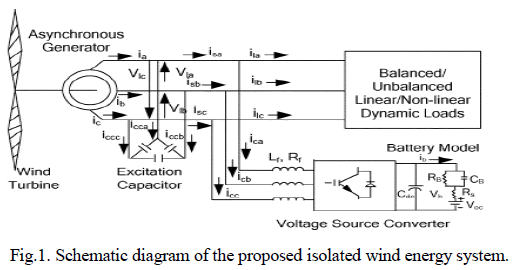
| The complete off grid stand alone system with asynchronous generator, wind turbine, excitation capacitor, balanced/ unbalanced, linear/non-linear/dynamic consumer loads and proposed controller is shown in Fig.1. The proposed controller includes three-phase insulated gate bipolar junction transistor (IGBT) based voltage source converter (VSC) along with a battery at its dc link. The controller is connected at the point of common coupling (PCC) through the inter-facing inductor [1]. The excitation capacitor is selected to generate the rated voltage at no-load while additional demand of reactive power is met by the controller. |
 |
| This wind energy system include |
A .EXCITATION CAPACITOR BANK |
| Autonomous induction generators are cheap, simple and robust. However, while they are capable to generate active power, they are unable to produce the reactive power needed for their own excitation. The classical solution to this problem is to connect capacitors across its stator terminals of the externally driven three-phase squirrel cage induction machine |
| Due to the three-phase capacitor bank connected to the induction generator an emf is induced in the machine windings due to the self excitation provided by the capacitors. The magnetizing requirement of the machine is supplied by these capacitors. For self excitation to occur, the following two conditions must be satisfied: |
| i.) The rotor of the machine should have sufficient residual magnetism. |
| ii.) The three-phase capacitor bank should be of sufficient value. |
| If an appropriate capacitor bank is connected across the terminals of an externally driven squirrel cage induction generator, and if its rotor has sufficient residual magnetism emf will be induced in the machine windings due to the excitation provided by the capacitors. This phenomenon is known as "capacitor self-excitation". If the induced emf is sufficient, leading currents through the capacitors will circulate. |
| The magnetic flux produced due to these currents would assist the residual magnetism in magnetizing the iron core of the induction generator. This would increase the machine main magnetic flux and larger emf will be induced. This in turn will increase both the currents and the flux. The induced voltage and the current will continue to rise until the reactive power supplied by the capacitors is balanced by the reactive power required by the induction machine, a condition which is essentially decided by the saturation of the magnetic cores. This process is thus cumulative and the induced voltage keeps on rising until saturation is reached. |
B.BATTERY ENERGY STORAGE SYSTEM |
| The proposed voltage and frequency controller is realized using IGBT (Insulated Gate Bipolar Junction Transistor) based voltage source converter (VSC) along with battery energy storage system (BESS) at its DC link. The proposed controller is having bidirectional flow capability of reactive and active powers because of which it can control the magnitude and frequency of the generated voltage under different electrical and mechanical dynamic conditions. Accordingly the principle of frequency regulation for generating constant frequency at fixed speed, the total generated power should be consumed by the applied load (consumer load battery) otherwise additional generated power might be stored in the revolving component of the machine and it increases the machine speed which in turns increases the system frequency. On the other hand when there is variation in wind speeds and corresponding variation in the machine speed, the battery and consumer loads absorb such amount of power by which desired frequency of the generated voltage can be achieved. |
| In proposed control scheme, the frequency controller is used for extracting active component of the source current. When there is deficiency in the generated power, the battery supplies the additional required load demand through process of discharging and maintains the constant frequency along with providing the functions of load levelling [16],[17] . While there is an excess generated power it starts charging and consumes additional generated power which is not consumed by the consumer loads. |
C.CAPACITOR BANK |
| The main drawback of the autonomous squirrel cage induction generator having a three-phase capacitor bank is the lack of ability to control the terminal voltage and frequency under non-constant load and speed conditions. Therefore, capacitor excited induction generators have poor voltage and frequency stability [2] . To regulate the voltage of an autonomous induction generator with changing load and speed, the capacitors may be replaced or supplemented with an active external source of reactive power [3] . Such a so-called solid-state synchronous voltage source is based on a dc-ac converter (or inverter), which is able to generate leading or lagging reactive power. Thus, inverters can be used as reactive power compensators for squirrel cage induction generator. |
CONTROL SCHEME |
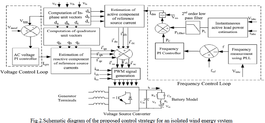
| Fig. 2 demonstrates the control strategy of the proposed controller which is based on the generation of reference source currents . Reference source currents are having two components one is reactive component for controlling the magnitude of the generated voltage and other one is the active component for regulating the frequency of the generated voltage. The amplitude of active power component of the source current is estimated by dividing the difference of filtered load power and output of PI frequency controller to the amplitude of the terminal voltage. Multiplication of with in-phase unit templates yields the in-phase component of reference source currents. These templates are, threephase sinusoidal functions which are derived by dividing the ac voltages by their amplitude. To generate the reactive component of reference source currents another set of unit templates is derived from in-phase unit template and which are 90 leading from the corresponding voltages. The multiplication of these templates and output of PI (Proportional– Integral) terminal voltage controller gives the reactive component of reference source currents .The sum of instantaneous reactive and active Components of currents gives the total reference source currents and these are compared with the sensed source currents . The amplified current error signals are compared with fixed frequency (10 kHz) triangular carrier wave to generate the PWM switching signals for the devices of VSC. |
 |
MODELING OF THE CONTROL SCHEME |
| Basic equations of the control scheme of the proposed controller are as follows. |
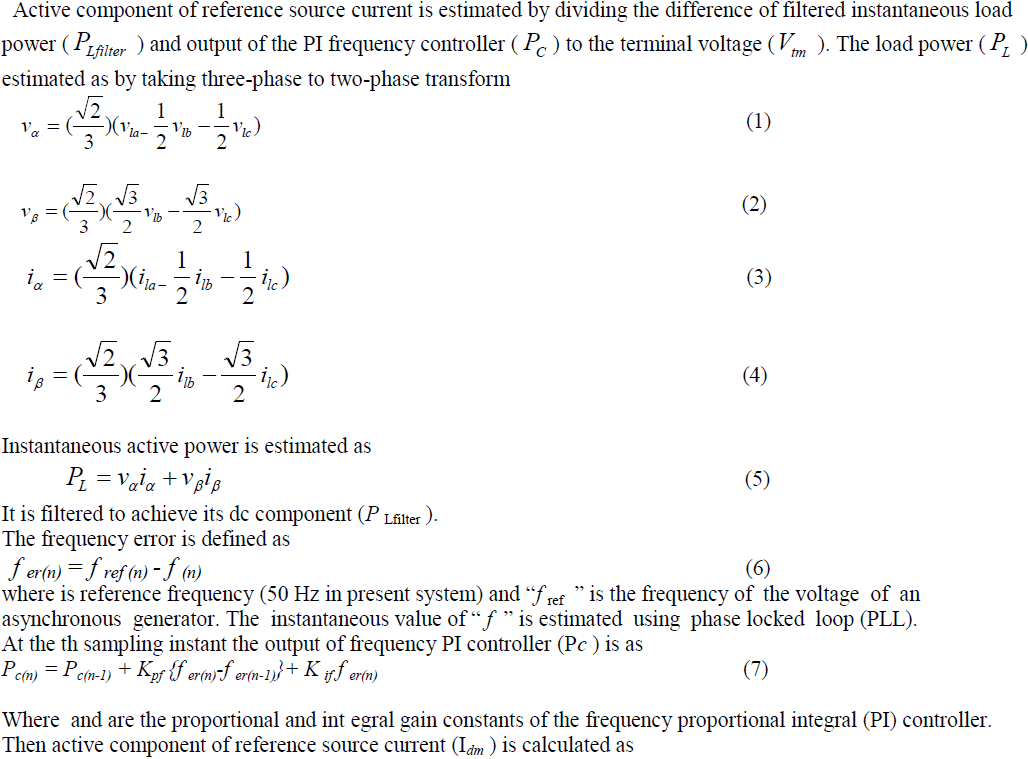
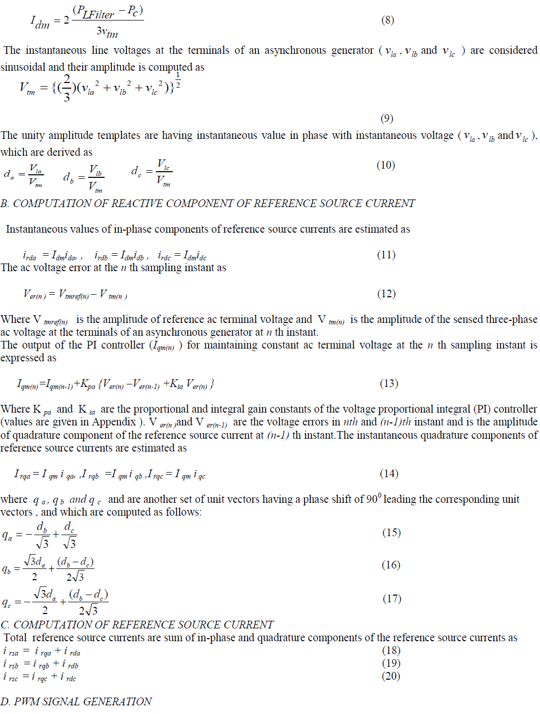
A. COMPUTATION OF ACTIVE COMPONENT OF REFERENCE SOURCE CURRENT |
 |
 |
 |
ANALYSIS AND DESIGN |
A.DESIGN OF THREE LEG VFC |
| Parameters of VFCs are designed for a 22-kW, 415-V, 50-Hz asynchronous generator-based standalone WECS. It is reported that for feeding reactive power in the case of 0.8-pf lagging reactive loads, an IAG requires 140–160% of the reactive power of the rated generated power. Therefore, the VAR rating of the VFC required for 22 kW (PA) generator is around 30 kVAR. |
| Then, the apparent power SA is given as |
 |
| On the basis of earlier current rating, the peak-to-peak current ripple (considering 5% of the peak current) through the filter inductor can be estimated as |
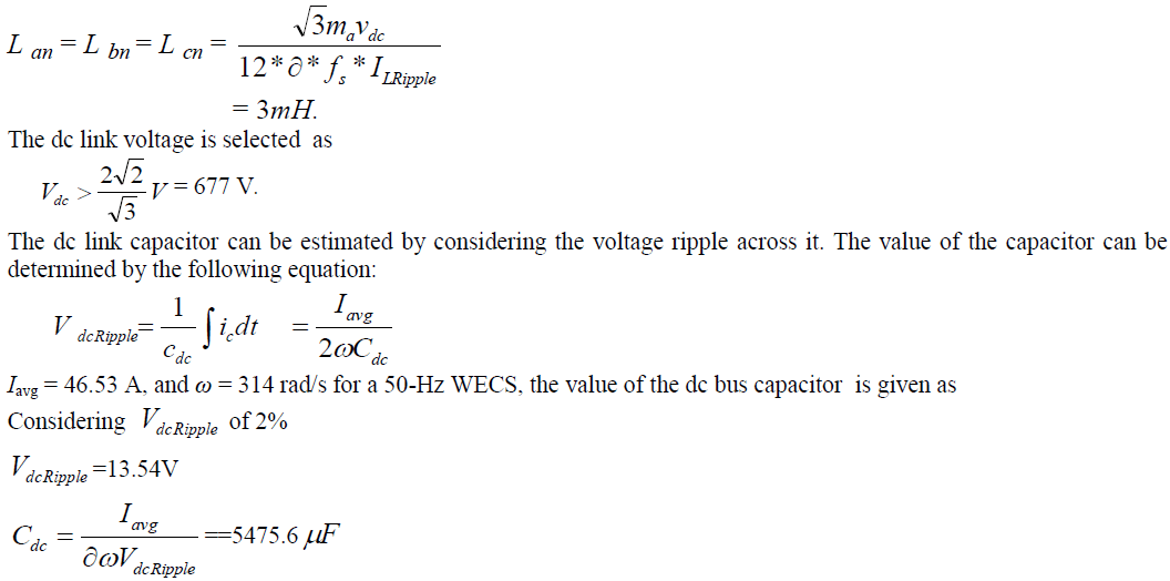
| By estimating this current ripple and the average value of the current, the value of filter inductors and dc link capacitors can be estimated for various VFC topologies as follows Here, the modulation index ma is considered equal to value of 1. The ripple current through the inductor is taken 5%Overloading factor ∂ due to transient condition varies from 120% to 180% The switching frequency of 10 kHz is selected for IGBTs of VSCs. |
| The filter inductor is calculated by substituting the values of parameters as |
 |
RESULTS AND DISCUSSION |
| Model with voltage and frequency control is modelled using MATLAB for linear- balanced and unbalanced, nonlinear- balanced and unbalanced loads. The results are given below and we can see distortion is very much reduced. |
A. PERFORMANCE OF THE CONTROLLER FEEDING LINEARLOADS |
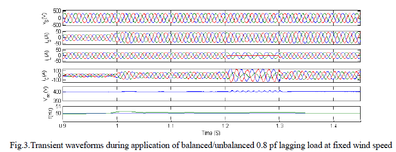
| Similarly Fig.3. demonstrates the performance of the controller with 0.8 pf lagging reactive loads (balanced and unbalanced respectively) at fixed wind speed. At 1 s load is given and at 1.2 s one phase of the load are opened and the load becomes unbalanced but voltage and current at the generator terminals remain balanced |
 |
B. PERFORMANCE OF THE CONTROLLER FEEDING NONLINEARLOADS |
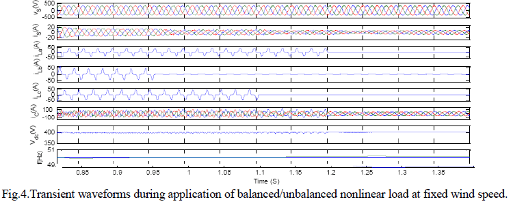
| Fig.4 demonstrates the performance of the controller with nonlinear load at fixed wind speed. A three-phase rectifier load with resistive element is applied and the generator terminal with minimal harmonic distortion which show the load balancing aspects of the controller. At 0.95 s one phase and later on at 1.1 s another phase of the load are opened and the load becomes unbalanced but voltage and current at the generator terminals remain balanced |
 |
C. PERFORMANCE OF THE CONTROLLER UNDER VARYING WIND SPEED |
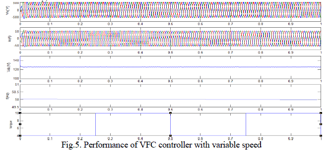
| Fig.5 shows the performance of the controller with varying wind speeds at constant applied consumer load. At 0 s when the wind speed is 4 m/s, a consumer load (18 kW) is applied at the generator terminals. Due to insufficient power generation at low wind speed, an additional load power is supplied by the battery to regulate the frequency. At 0.25 s as the wind speed is increased from 4 m/s to 10 m/s here also the controller provides the load levelling and control of the frequency of the generated voltage. |
 |
CONCLUSION |
| The performance of the proposed controller has been demonstrated for an isolated wind energy conversion system. Simulation results have verified the performance of the controller under different electrical (varying consumer loads) . It has been observed that the proposed controller has been found to regulate the magnitude and frequency of the generated voltage constant in isolated wind power application. The proposed voltage and frequency controller has also been found capable to function as a harmonic compensator, a load balancer and a load leveller. |
ACKNOWLEDGMENT |
| The authors acknowledge gratefully for the support of Electrical and Electronics Department of M.A College of Engineering, Kothamangalam. |
References |
|