ISSN ONLINE(2278-8875) PRINT (2320-3765)
ISSN ONLINE(2278-8875) PRINT (2320-3765)
Devendra Kumar Sahu1, Ankit Dubey2
|
| Related article at Pubmed, Scholar Google |
Visit for more related articles at International Journal of Advanced Research in Electrical, Electronics and Instrumentation Engineering
In the present scenario the power system are operated nearer to their stability limits due to economic and environmental reasons. Now days a stable and secure operation of a power system is therefore a very important and challenging issue. Efficient transmission of voltage and stable operation of the power system is very much essential. The stability has been given much attention by power system researchers and planners in recent years, and is being regarded as one of the major sources of power system problems and insecurity. To compensate these problems in transmission system svc is used. A static VAR compensator is chosen as a low cost solution to replace a conventional capacitor bank, thus allowing a continuous and flexible nodal voltage adjustment. Due to simplest structure, easy designing and low cost, PI controller is used in SVC as voltage regulator is used to regulate the voltage in most industries. In this paper shunt FACTS device-SVC is used in transmission line for improving the voltage profile and stability. MATLAB Simulink platform has been used in this study.
Keywords |
| shunt device, transmission line, MATLAB, SVC, voltage stability. |
INTRODUCTION |
| Static VAR Compensators can be very effective in controlling voltage fluctuations at rapidly varying loads. Unfortunately, the price for such flexibility is high. Nevertheless, they are often the only cost-effective solution for many loads located in remote areas where the power system is weak [2]. In the present scenario the demand for electrical energy has very much intense. This has led to the facing of power transmission limitation crisis by energy transmission systems. The limitations occur due to maintaining a balance between supplying the allowed level of voltage and maintaining stability of the system. Voltage stability is severe problem, which steadily reach operating limits imposed by economic and environment conditions. Whenever there is change in load or fault the system voltage level changes. With the drop in voltage level, the reactive power demand increases. If the reactive powers demand is not met, then it leads to furtherer decline in bus voltage resulting in the cascading effect on neighbouring regions. |
| As the disturbance are arises in the system due any abnormal condition of fault, it goes to transient oscillations. These unwanted oscillations can change the performance characterics of applications. Hence this is required to control and is done by the use the same shunt FACTS device Static VAR Compensator (SVC) designed with auxiliary controllers [9]. Therefore SVC is more effective and if accommodated with supplementary controller, by adjusting the equivalent shunt capacitance, SVC will damp out the oscillations and improves the overall system stability [10]. The system operating conditions change considerably during disturbances. Various approaches are available for designing auxiliary controllers in SVC. In [11] a proportional integral derivative (PID) was used in SVC. It was found that significant improvements in system damping can be achieved by the PID based SVC. Although PID controllers are simple and easy to design, their performances deteriorate when the system operating conditions vary widely and large disturbances occur. |
| Hence there is a requirement of devices which can control the random fluctuations and the transient oscillations comes in the transmission line voltage during transmission. It is necessary that system has very less overshoot and very less settling time for retain of voltage in steady level. So for this from the last few years static VAR compensator plays an important role in voltage regulation in AC Transmission Systems. A Static VAR Compensators provides such system improvements and benefits by controlling Shunt reactive power sources, both capacitive and inductive, with fast power electronic switching devices. The shunt connected, fixed or mechanically switched reactors are applied to minimize the line overvoltage under light load condition, and shunt connected, fixed or mechanically switched capacitors are applied to maintain voltage levels under the heavy load conditions [1]. |
STATIC VAR COMPENSATOR |
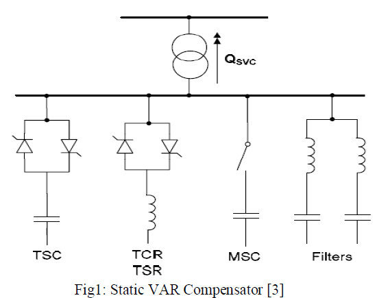
| According to definition of IEEE PES Task Force of FACTS Working Group: Static VAR Compensator (SVC): A shunt connected static VAR generator or absorber whose output is adjusted to exchange capacitive or inductive current so as to maintain or control specific parameters of the electrical power system (typically bus voltage). This is a general term for a Thyristor Controlled Reactor (TCR) or Thyristor Switched Reactor (TSR) and/or Thyristor Switched Capacitor (TSC) Fig 1. The term, “SVC” has been used for shunt connected compensators, which are based on thyristors without gate turn-off capability [3]. It includes separate equipment for leading and lagging VARs; the thyristor–controlled or thyristor – switched reactor for absorbing reactive power and thyristor – switched capacitor for supplying the reactive power. |
 |
SVC V-I characteristics |
| The SVC can be operated in two different modes: |
| In voltage regulation mode (the voltage is regulated within limits as explained below). |
| In VAR control mode (the SVC susceptance is kept constant) |
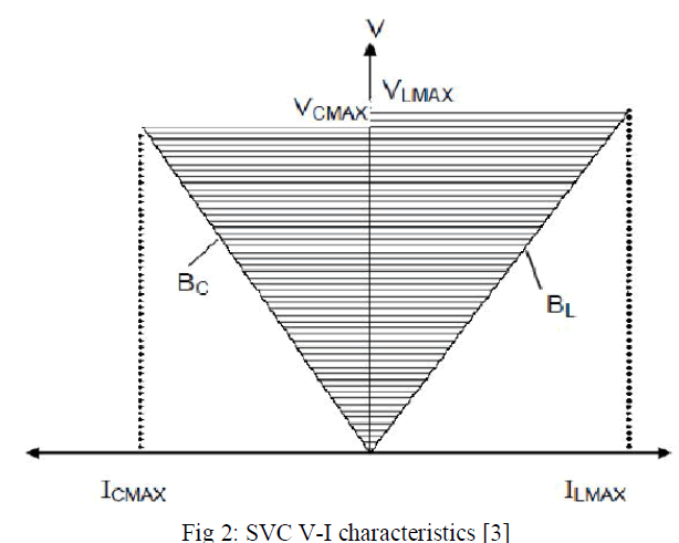
| When the SVC is operated in voltage regulation mode, it implements the V-I characteristic as shown in Fig. (2). As long as the SVC susceptance B stays within the maximum and minimum susceptance values imposed by the total reactive power of capacitor banks (Bcmax) and reactor banks (Blmax), the voltage is regulated at the reference voltage Vref. However, a voltage droop is normally used (usually between 1% and 4% at maximum reactive power output), and the V-I characteristic has the slope indicated in the Fig. 2 [8]. |
 |
Control Concept of SVC |
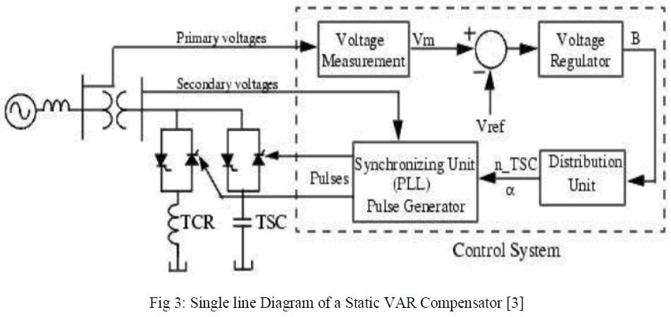
| The control concept of svc is based on controlling of shunt susceptance (B) which can be controlled by changing the firing angle of thyristor. The control objective of the SVC is to maintain a desired voltage at the high-voltage bus. The SVC regulates voltage at its terminals by controlling the amount of reactive power injected into or absorbed from the power system. When system voltage is low, the SVC generates reactive power (SVC capacitive). When system voltage is high, it absorbs reactive power (SVC inductive). The variation of reactive power is performed by switching threephase capacitor banks and inductor banks connected on the secondary side of a coupling transformer. Each capacitor bank is switched on and off by three thyristor switches (Thyristor Switched Capacitor or TSC). Reactors are either switched on-off (Thyristor Switched Reactor or TSR) or phase-controlled (Thyristor Controlled Reactor or TCR). Fig.3 shows a single-line diagram of a static VAR compensator and a simplified block diagram of its control system [8]. The control system consists of |
| A measurement system measuring the positive-sequence voltage to be controlled. A Fourier-based measurement system using a one-cycle running average is used. |
| A voltage regulator that uses the voltage error (difference between the measured voltage Vm and the reference voltage (Vref) to determine the SVC susceptance B needed to keep the system voltage constant. |
| A distribution unit that determines the TSCs (and eventually TSRs) that must be switched in and out, and computes the firing angle α of TCRs. |
| A synchronizing system using a phase-locked loop (PLL) synchronized on the secondary voltages and a pulse generator that send appropriate pulses to the thyristors. |
 |
SVC Modelling |
| The Static VAR Compensator is basically a shunt connected variable VAR generator whose output is adjusted to exchange capacitive or inductive current to the system. One of the most widely used configurations of the SVC is the FC- TCR type in which a Fixed Capacitor (FC) is connected in parallel with Thyristor Controlled Reactor (TCR). The magnitude of the SVC is inductive admittance BL (α) is a function of the firing angle α and is given by [2, 3]: |
 |
| A rapidly operating Static VAR Compensator (SVC) can regularly provide the reactive power necessary to control dynamic voltage swings under different system conditions and thereby improve the power system transmission and distribution performance. Installing an SVC at one or more appropriate points in the network will enhance transfer capability through improved voltage stability, while maintaining a smooth voltage profile under different network conditions. In addition, an SVC can diminish active power oscillations through voltage amplitude modulation [3]. |
METHODOLOGY |
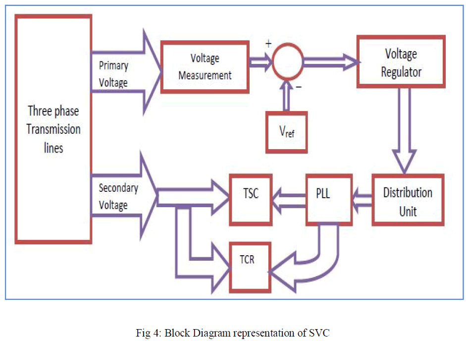
| The Static VAR Compensator is basically a shunt connected variable VAR generator whose output is adjusted to exchange capacitive or inductive current to the system. One of the most widely used configurations of the SVC is the FC- TCR type in which a Fixed Capacitor (FC) is connected in parallel with Thyristor Controlled Reactor (TCR). The block diagram of SVC voltage regulator is shown in the Fig.4 With the help of block diagram representation. The SVC control system consists of the following four main modules: |
| i. Measurement System measures the positive-sequence primary voltage. This system uses discrete Fourier computation technique to evaluate fundamental voltage over a one-cycle running average window. The voltage measurement unit is driven by a phase-locked loop (PLL) to take into account variations of system frequency. |
| ii. Voltage Regulator uses a PI regulator to regulate primary voltage at the reference voltage (1.0 pu specified in the SVC Controller block menu). A voltage droop is incorporated in the voltage regulation to obtain a V-I characteristic with a slope (0.01 pu /100 MVA). Therefore, when the SVC operating point changes from fully capacitive (+300 Mvar) to fully inductive (-100 Mvar) the SVC voltage varies between 1-0.03=0.97 pu and 1+0.01=1.01 pu. |
| iii. Distribution Unit uses the primary susceptance Bsvc computed by the voltage regulator to determine the TCR firing angle α and the status (on/off) of the three TSC branches. The firing angle α as a function of the TCR susceptance BTCR is implemented by a look-up table from the equation |
 |
| Where BTCR is the TCR susceptance in pu of rated TCR reactive power (109 Mvar). |
| iv. Firing Unit consists of three independent subsystems, one for each phase (AB, BC and CA). Each subsystem consists of a PLL synchronized on line-to-line secondary voltage and a pulse generator for each of the TCR and TSC branches. The pulse generator uses the firing angle α and the TSC status coming from the Distribution Unit to generate pulses. The firing of TSC branches can be synchronized (one pulse is sent at positive and negative thyristors at every cycle) or continuous. The synchronized firing mode is usually the preferred method because it reduces harmonics faster. |
 |
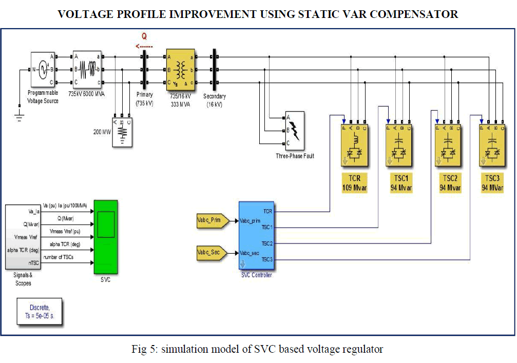 |
RESULTS & DISCUSSIONS |
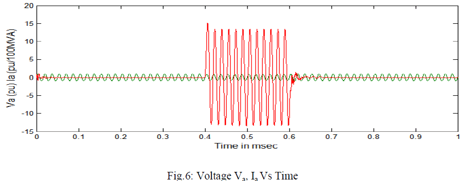
| The efficient regulation of voltage with the help of Static VAR Compensator based voltage regulator has been successfully studied and implemented in the Simulink. This section deploys the results obtained and steady state and dynamic performance analysis of results obtained. For the efficient Voltage regulation the reference voltage is taken as 1.0 pu. The Waveforms of Fig. 6 illustrates the SVC voltage regulator Dynamic Response to System Voltage variations. |
| In the figure 6 shows the waveform of a voltage Va and current Ia verses time across the three phase transmission line subjected to the three phase to ground fault when the system is controlled by the conventional system. The fault is introduced at time of 0.4 m sec and so voltage goes down the current is increased suddenly. |
 |
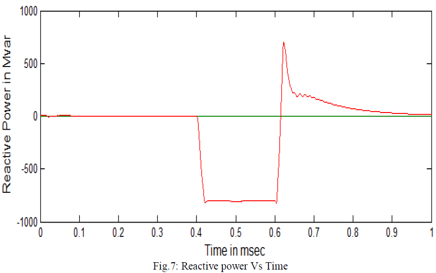
| Figure 7 shows the waveform of reactive power Vs time. The fig shows that at the time of fault introduced, the system demanded reactive power from input supply. |
 |
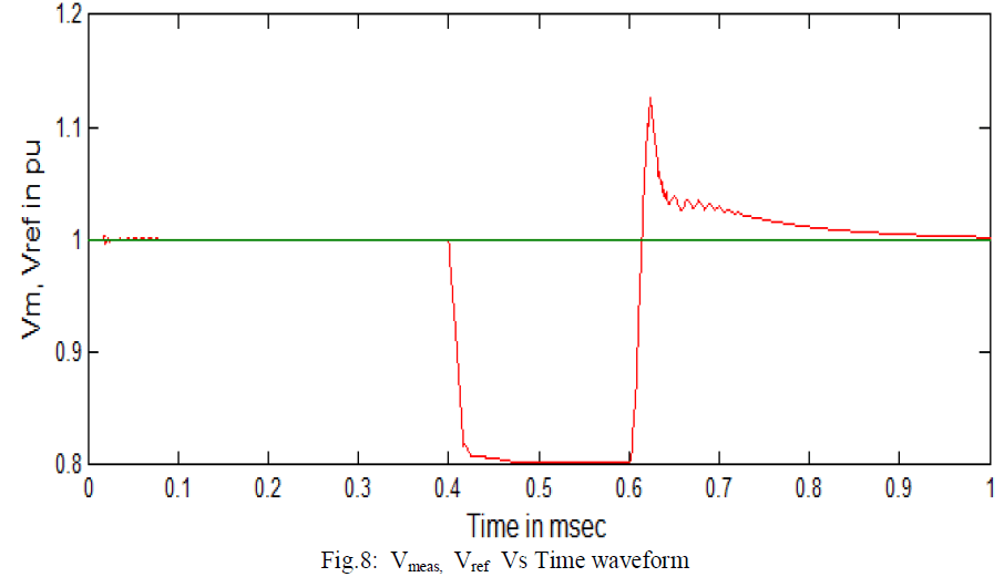
| Figure 8 shows the waveform of measured voltage Vmeas, reference voltage Vref and time. The reference voltage is set to 1.0 pu. In normal operating condition the measured voltage follows the reference voltage 1.05 pu, at the time of fault between t = 0.4 m sec to 0.6 m sec the voltage goes down. After 1.2 sec the svc control system activated and return back to the voltage caused overshoot from 1.12 pu to 1.0 pu at the time of 1.8 sec. |
 |
| Figure 9 shows the variation in TCR angle α with respect to the time. At the time of fault The TCR start to trigger at 172° and finally reaches with 180° at no conduction state as all three TSCs are working. |
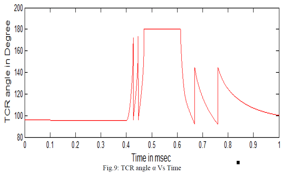 |
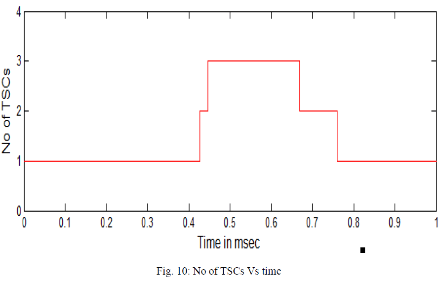
| As the fault occurs at 0.4 m sec the TCR start to trigger and generate a firing pulse to switched on the TSCs. After this point the three TSCs are in service and the TCR absorbs approximately 40% of its nominal reactive power. Observe on the last trace of the scope how the TSCs are sequentially switched on and off. Each time a TSC is switched on the TCR alpha angle changes suddenly from 180 degrees (no conduction) to 90 degrees (full conduction). Finally, at t=0.63 m sec the voltage is reached to 1.0 pu and the SVC reactive power is reduced to zero. |
 |
CONCLUSION |
| In this paper steady state and dynamic response of the transmission line voltage is studied by making the Simulink model in MATLAB platform. The usefulness of SVC has been studied in improving the voltage profile and voltage regulation of the transmission lines. In current scenario the equipments are very much sensitive to supply voltage fluctuation. Any kind of fluctuation either damage the costly equipment or may harm full for further used equipments. As the fault occurs in the system voltage fluctuates and with the help of SVC, the voltage finally attains steady value. The results obtained with the Static VAR Compensator shows that developed method is rigid against the random voltage fluctuations in transmission line, and provides an efficient voltage regulation. But we see that after clearing the fault high transients had appeared in transmission line voltage and power which affect the performance of connected applications. This is not easily handled by simple SVC system; we require some supplementary control system which handles this problem efficiently. |
References |
|