International Journal of Innovative Research in Computer and Communication Engineering
ISSN ONLINE(2320-9801) PRINT (2320-9798)
ISSN ONLINE(2320-9801) PRINT (2320-9798)
Antara Ghosal1, Anurima Majumdar2, Sisir Kumar Das3, Annapurna Das4
|
| Related article at Pubmed, Scholar Google |
Visit for more related articles at International Journal of Innovative Research in Computer and Communication Engineering
This paper describes the analysis and design of a class of square spiral microstrip antennas for broad frequency band and multi-frequency operations by adding suitable tuning elements in a single structure. The simulation and modeling of these configurations have been done using Ansoft HFSS software. The resonant frequencies and dimensions are computed from the cavity model of square patch. The parameters of antenna such as return loss, VSWR, radiation patterns and gain have been found and design is optimized for best results.
Keywords |
| Coaxial feed, square spiral microstrip patch antenna, wideband, multifrequency. |
INTRODUCTION |
| Microstrip spiral patch are analyzed by many authors [1, 2, 3, and 4]. Usually such antennas have narrow band width. Bernard [5] has shown that the area of a square patch is reduced by forming a square spiral and two adjacent spiral arms are shorted as tuning elements to obtain dual frequency operation and best return loss is obtained as -14 dB. The author [5] has not described fully about the co-axial feed design and its impedance matching. This paper described the design of square spiral shaped patch antennas operable over a wide frequency range or at multi-frequencies where suitable tuning elements are introduced. Broad band operation is useful in broad band communications and the multi - frequency operations are useful for multi-band mobile handsets. Ansoft HFSS software is used for analytical modelling and simulation |
II. ANALYSIS OF SQUARE SPIRAL MICROSTRIP ANTENNAS |
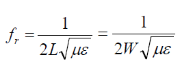
| The spiral structure makes the antenna more light weight and produces broad band operation. Fundamental resonant frequency is determined from the basic square patch using cavity model [1-3]. A square patch with edge length L=W= half guide wave length is shown in Fig.1. This produces two degenerate modes TM 010 and TM 100 having same resonant frequency: |
 (1) (1) |
| Here m=1, 3, 5… and n=1, 3, 5…. . For m, n =even, no bore site radiation will be obtained. |
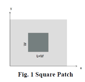 |
Depending on the excitation, only fringing fields at the edge parallel to x-axis or y-axis, produce bore site radiation in space which forms an array of two slots separated by a distance / 2 eff W ïÃâ¬Ã« ïÃÂÃâWïÃâûλ as shown in Fig.1. Here ïÃÂÃâW ïÃâû his the extra length due to fringing field extension [1]. the extra length due to fringing field extension [1]. |
III. SIMULATION AND MODELLING |
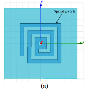
| The time when no path is available to transmit the packet is considered as the network lifetime. In the present paper area of the patch is kept same as that of square patch but the total metal of the patch is reduced by forming the spiral. HFSS modelling and analysis are carried out for the structure where capacitive coupled tuning elements between successive spiral arms are used for wide band operation. |
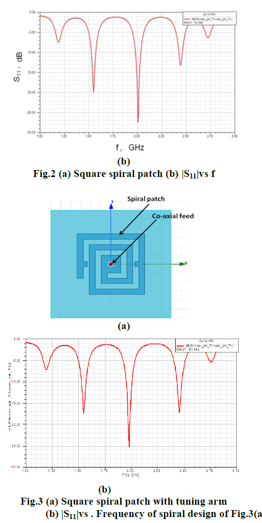
| The design parameters are: W=L=33.7mm, h=1.6mm. and substrate r ïÃÂÃÂ¥ = 4.4. The patch is excited from the back with a co-axial line probe. The probe position is optimized at the centre of the spiral ( 0mm ,0mm ,0mm) for best impedance matching with the 50 ohm feed line . The ratio of the radii of the inner and outer conductor of the coaxial line is 3.5 for 50 ohm input impedance and it is computed using FR4_epoxy. The inner conductor radius is taken as 0.5 mm and the outer conductor radius is taken as 1.75 mm. |
| From the above design of Fig 3 (a), multi- frequency response with very good return losses (better than -17 dB) at 1.58GHz, 2.02 GHz and 2.47 GHz is obtained as shown in Fig.3(b). Therefore, the configuration with symmetrical tuning elements at the outer most spiral arms produces three distinct resonant frequencies which could be received by this antenna. ( |
 |
 |
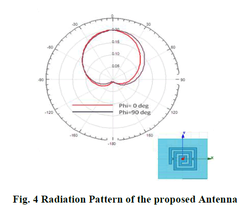
| The radiation patterns of these configurations are also obtained from simulation results and found they are in good shape for bore side radiation as shown in Fig.4. |
 |
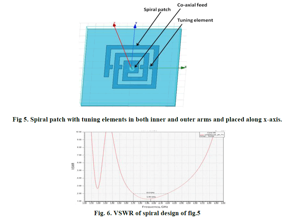
| A different type of capacitive tunning elements are now placed along x-axis in both inner and outer arms as shown in Fig. 5. A remarkable observation is made that symmetrical tuning elements result in very broadband VSWR performance as shown in Fig. 6. It is observed that although the centre frequency is shifted from 2.1 GHz to 1.95GHz, a wideband operation of 25.6% bandwidth is obtained for the VSWR ≤ 2. |
 |
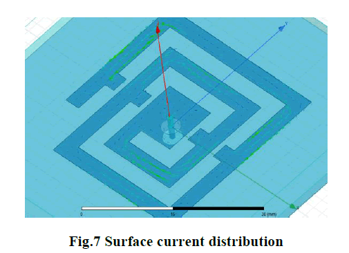
| The electric current distributions are also shown in Fig.7 to support the bore side radiation characteristics |
 |
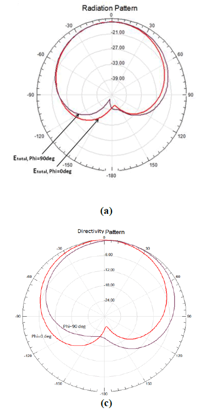
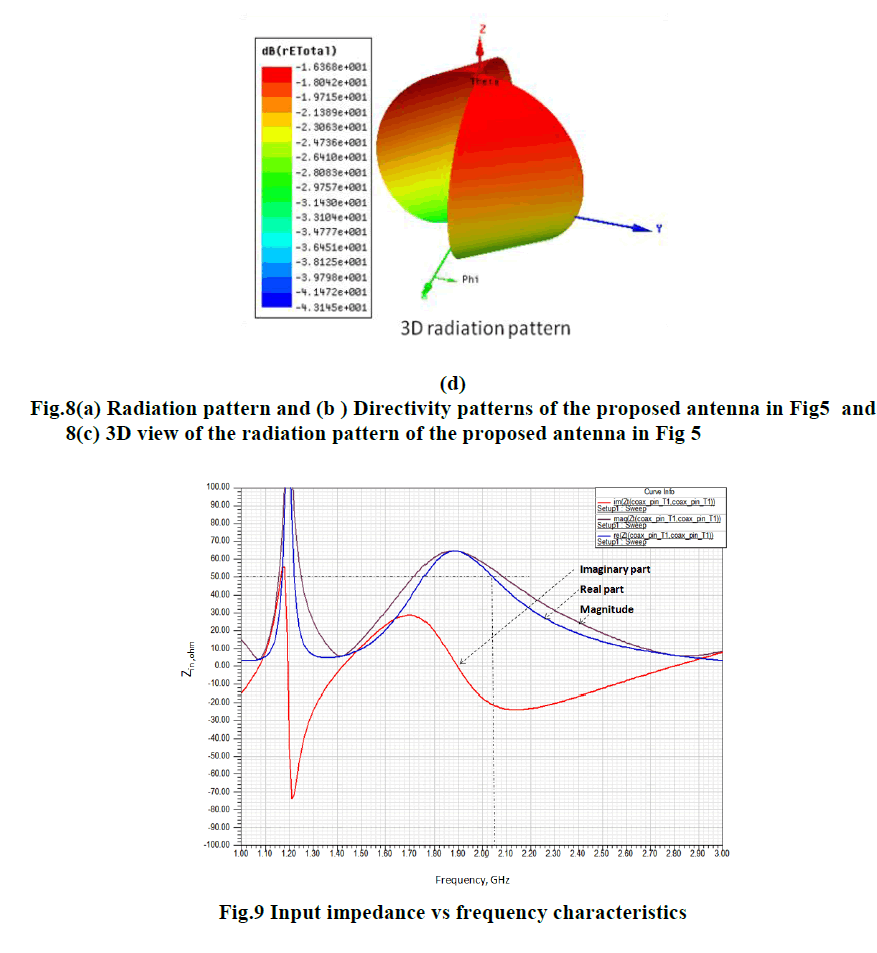
| Therefore, a novel design is made such that different tuning arrangements in a square spiral patch produce multifrequency and also wideband antenna performances. The radiation patterns in different planes and its directivity characteristics are shown in Fig.8. The input impedance vs. frequency characteristics (Fig.9) show that the spiral is well matched to co-axial feed at 2.05 GHz. |
 |
 |
CONCLUSION |
| This paper described the design of square spiral shaped patch antennas operable over a wide frequency range or at multi-frequencies by incorporating suitable tuning elements. Ansoft HFSS software is used for analytical modelling and simulation. A good impedance matching is observed near the frequencies 1.6 GHz, 2 GHz, and 2.4 GHz using two symmetrical tuning elements as shown in Fig. 3 for the multifrequency operation of mobile hand set. The same antenna with four symmetrical tuning elements (Fig.5) can be used for broad band communication over a band width of 25.6%. |
References |
|