ISSN ONLINE(2319-8753)PRINT(2347-6710)
ISSN ONLINE(2319-8753)PRINT(2347-6710)
A.M. Pawar1, S. N. Patil1, A. S. Powar1 and B. P. Ladgaonkar2
|
| Related article at Pubmed, Scholar Google |
Visit for more related articles at International Journal of Innovative Research in Science, Engineering and Technology
Precision agriculture is an innovative technology, wherein the crops are cultivated in controlled environment. Emphasizing the need of precision agriculture, an electronic system is designed to provide thermal comfort to the crops of polyhouse environment, wherein an ubiquitous technology, Wireless Sensor Network (WSN) is deployed. To realize the establishment of wireless sensor network, a wireless sensor node is designed using embedded philosophy and presented in this paper. Availing promising features of AVR ATmega 8L microcontroller, the wireless sensor node is designed to monitor the thermal status of the polyhouse environment in spatio-temporal domain. The precision temperature sensor LM35 is employed to read the thermal status. Moreover, the signal conditioning circuit is wired about TLC 271, which operates on one power supply only and exhibiting very high input impedance with rail to rail input. An analog signal is digitized with on chip analog to digital converter with 10 bit resolution. The controlling unit is also designed to activate the heater as well as ventilators. To ensure wireless communication, the Zigbee model from Digi corporation is deployed as RF module. The sensor nodes are calibrated to the real unit and its performance is confirmed by comparing the results with standard digital thermometer. Each sensor node is assigned with network ID and it communicates the data with the respective ID in star topology. The present wireless sensor network is deployed in the polyhouse to monitor thermal status. It works continuously and precisely to hold control on temperature of the domain with great reliability.
Keywords |
| Wireless Sensor Network, Zigbee Technology, Embedded System, AVR ATmega 8L microcontroller. |
I. INTRODUCTION |
| The emergence of Wireless Sensor Network plays vital role for ubiquity of the electronic instrumentation [1]. In modern agriculture, the polyhouse technology is significantly adopted, which leads to enhance the productivity of the crops. In polyhouse technology, the crops are cultivated in the controlled environment [2]. Therefore, tracing of conditions of parameters within localized domains and monitoring of the same is essential to ensure the automization in the polyhouse agriculture. Continuous monitoring of the environmental parameters gives information to the user to understand the effect of each parameters on the growth and yield. The polyhouse climate monitoring and control can enable the farmers to improve productivity and to achieve remarkable energy saving. During summer season the temperature must be controlled by controlled ventilation, whereas during winter season, a thermal comfort within spatio-temporal domain must be provided to the crops. |
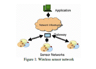
| To monitor such parameters more precisely, sophisticated electronic system is needed. An innovative technology, wireless sensor network (WSN), can provides suitable solution and assists the precision agriculturist to ensure modernization in the polyhouse agriculture [3]. Wireless Sensor Network (WSN) is the distributed network [figure1] comprising fundamental units called sensor nodes [4], which are wirelessly routed with the typical topology. The wireless sensor network collaboratively collects the data from the sensor nodes, configured as End Device and communicated to the centralized system, equipped with the Coordinator, to monitor the data and to control the same as well [5]. As compared with wired network, the wireless network is more pervasive, low cost, easy, low power and exhibit lowest time to market. One of the key features of wireless sensor network is that, it facilitates reconfiguration, self insert and self healing of the nodes into network, wide area coverage etc. [6]. |
 |
| The wireless sensor network is designed, using star topology, to establish a thermal comfort within the polyhouse environment and the results are interpreted in this paper. |
II. REVIEW OF LITERATURE |
| Emphasizing the cultivation of tomato crop in polyhouse, Mancuso et al have developed wireless sensor network to monitor air temperature, relative humidity and soil temperature [7]. They have extended their design for web-based applications, by employing internet communication protocol and GSM module. Liu et al have developed and tested a wireless sensor network prototype for monitoring polyhouse environment [8]. They availed Micaz nodes in star topology. They deployed ARM microcontroller to develop the base station to display the data on LCD. Naresh Kumar et al have developed ARM microcontroller based system to monitor environmental parameters [9]. They deployed Zigbee as RF module to ensure the wireless sensor network. Wireless Sensor Network is reported by Uprety et al for monitoring of carbon dioxide gas concentration, as per the requirement of the crop [10]. Based on AVR microcontroller the wireless sensor network is designed by Song et al for greenhouse and interpreted the results of comparative study of various networking topologies [11]. |
| To enhance the features of wireless sensor network, the smart sensor nodes have been designed by Haefke et al [12]. They deployed an integrated temperature sensor, DS600 from maxim, having 6.4 mV/0C temperature coefficient and good linearity within -40 0C to 120 0C. |
| In order to provide thermal comfort within indoor environment a smart wireless sensor network is designed and reported by Kumar et al [13]. They claimed its advantages over traditional Heating Ventilating Air Conditioning (HVAC) system. Erdon et al [14] have developed wireless sensor to monitor pressure inside a tyre of automobiles. Li and Yuan used the wireless sensor network for waste water monitoring system [15]. Wireless smart camera network is developed by Zivkovic [16], wherein zigbee module used for wireless data communication. One of the major applications of the sensor network is the agriculture field, which is backbone of economy for many nations. The perception, processing, integration and application of information etc are the main content of agricultural environment information technology [17]. |
| Present investigation emphasizes the development of wireless sensor network, wherein reliability of sensor nodes, plays vital role. It realizes an embedded system designed about promising microcontroller [19]. Therefore, to establish wireless sensor network, the designing of sensor node for dedicated application is prime requirement. The general architecture of the sensor node consists of advanced microcontroller as computing device and analog part of the hardware for sensing and acquisition of the signals. To ensure wireless communication, the sensor node employs RF module [19]. |
| In this paper, the details about designing of sensor nodes, for wireless sensor network to provide thermal comfort to the crops of polyhouse are interpreted. As it is embedded system, both hardware as well as firmware of present sensor node is designed. |
III. HARDWARE |
| Novel wireless sensor network for agricultural application requires sophisticated electronic instrumentation that monitors the information of environmental parameters [20]. According to the general architecture, the wireless sensor network exhibit the designing of wireless sensor node and the development of base station. The hardware for both parts have been designed and presented through the block diagram and circuit schematic. The block diagram showing design of wireless sensor node, the End Device, is depicted in figure 2.a. |
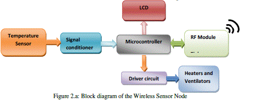 |
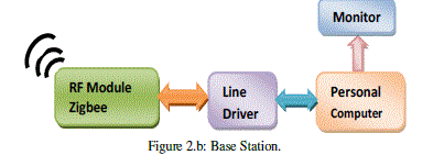
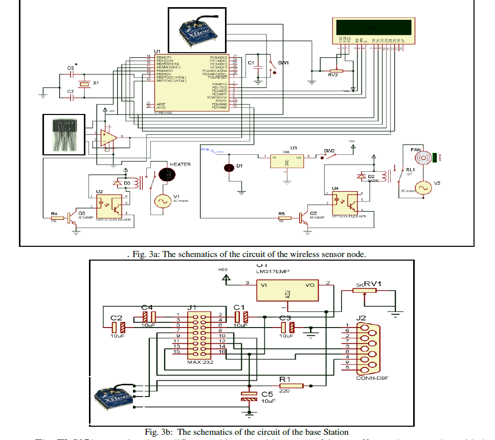
| Moreover, figure 2.b represents the block diagram of the coordinator node, designed to establish communication with the PC. The schematic of the circuit is presented in figure 3. |
 |
| As shown in figure 2.a, the sensor node is designed to sense as well as to control the thermal conditions of the typical area under coverage of the respective nodes. Therefore, it comprises sensing system as well as controlling electronics. The details regarding designing aspects are discussed through following points. |
| a) Wireless Sensor node [The End Device]: The sensor nodes play key role in the functioning of wireless sensor network [12]. The circuit of sensor node, shown figure 3, has two parts, the sensing the thermal condition in spatio-temporal domain and the actuation of the drivers connected to the heating and ventilating arrangement. The smart Heating Ventilating Air Conditioning system also depicts this technology [18]. Ensuring the facets of the embedded design, the sensor node is designed, wherein the temperature sensor, signal conditioner, microcontroller, RF section, driver and control unit, display device etc, stages have been incorporated. |
| i) Temperature Sensing: The thermal condition is sensed by employing highly precise temperature sensor LM 35. It exhibit good linearity over wide temperature range and provides temperature dependent emf with 10mV/0C, temperature coefficient [21]. The LM 35 does not require any external trimming for calibration. It provides, typically, the accuracy of ±1⁄4°C at room temperature and ±3⁄4°C over full, -550c to +1550c, temperature range. Hence, deployment of LM 35 to readout and control circuitry is recommended. It draws only 60 A current [21]. |
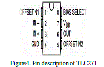
| ii) Signal Conditioner: The signal conditioning circuit is wired to provide temperature dependent voltage. The operational amplifier TLC 271 is used to interface the analog signals. The operational amplifier, TLC 271, exhibit very high input impedance and hence, it is most suitable to wire such sophisticated system. An important characteristic of this TLC 271 is that, it operates on single power supply and has rail to rail input as well as output [22]. The pin description of the TLC 271 is shown in figure 4. |
 |
| The TLC271 operational amplifier combines a wide range of input offset voltage grades with low offset voltage drift and high input impedance. In addition, the TLC271 offers a bias-select mode that allows the user to select the best combination of power dissipation and ac performance for a particular application. These devices use Texas Instruments silicon-gate LinCMOS technology [22]. Output of the signal conditioning stage is given to the analog channel of the microcontroller. The AVR ATmega 8L has provision to deploy internal source of 2.56V as reference for on-chip ADC. Therefore, to ensure full range of operation, the gain of signal conditioning stage is limited to 1. It provides better solution for buffering of the signal. |
 |
| The microcontroller digitizes the signal with 10 bit resolution and processes the same for further action. iii) Microcontroller AVR ATmega 8L: The present sensor node realizes the embedded system, which is wired about AVR ATmega 8L microcontroller. This is advanced microcontroller having promising on-chip resources. |
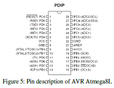
| Figure 5 depicts the pin description of AVR ATmega 8L [23]. The salient features of microcontroller AVR ATmega 8L, who helps to develop very smart embedded system is as below |
 |
| It has RISC instruction set with 32 general purpose working registers |
| 8 Kbytes of In-system programmable flash with read while write capabilities |
| 512 bytes of EEPROM |
| 1K byte of SRAM |
| 23 general purpose I/O lines |
| a 8-channel ADC with 10-bit resolution |
| a byte oriented Two-wire Serial Interface |
| a programmable Watchdog Timer with Internal Oscillator |
| a serial programmable UART |
| an SPI serial port |
| five software selectable power saving modes |
| internal and external interrupts |
| Three flexible Timer/Counters with compare/capture modes |
| The deployment of on chip resources of the AVR microcontroller such as ADC, I/O ports, memories etc. helps to reduce complexity, cost and time to market as well. The AVR ATmega 8L microcontroller reads analog signal and digitizes to 10 bit resolution using on chip ADC. Use of ADC with 10 bit resolution, leads to enhance the accuracy in the observations. The signal is coupled to channel 0 of on-chip ADC, which is configured in right justified mode. The digital data is available in two resistors ADRESH and ADRESL, which is further packed by the expression given below. |
| Digital output (DT) = (ADRESH*256) +ADRESL … (1) |
| Thus, obtained digital data is converted into real voltage form by the expression |
| VT = (Vref/1024)* DT … (2) |
| Where, the reference voltage, Vref, is configured to 2.56V internal. Configuration of highly stable internal reference voltage to 2.56V results into highly precise and stable data. The emf obtained from expression 2 is used for the process of calibration and conversion of data into real unit, the unit of temperature. |
| iv )The Display Section: The 16*2 lines smart LCD is interfaced to ensure digital readout of thermal condition at respective domain. The LCD is configured in sleep mode, which helps to save the power. Through RF section, the thermal status of the domain is also communicated to the base station. |
| v) RF Unit: To ensure the establishment of wireless sensor network, the RF section plays vital role. The section is designed about zigbee, the RF module, launched by Digi Corporation and operates within ISM band and supports IEEE standard 802.15.4 [24, 25, 26]. The salient features of this zigbee device are as mentioned below |
| RF data rate: 250 Kbps |
| Operating frequency: 2.4 GHz |
| 63 mW (+18 dBm) North American version |
| Indoor/Urban range: Up to 300 ft (90 m) |
| Outdoor/RF line-of-sight range: Up to 1 mile (1.6 km) |
| Interface data rate: Up to 115.2 Kbps |
| Receiver sensitivity: -100 dBm (all variants) |
| 2mW (+3 dBm) boost mode |
| vi) Controlling unit: Emphasizing the objective of controlling of temperature of polyhouse environment, the controlling is designed and deployed. It consist of two parts Heater and Ventilator. To ensure the driving of this control units, two lines of Port D of microcontroller AVR ATmega 8L are assigned. It is found that simple room heater consume more power. Due to heavy current controlling of the same become tedious. It also creates the problem of back emf. Therefore, to increase the temperature, an incandescent lamp is employed. The optocoupler MCT 2E is used to isolate the heater from microcontroller. Ensuring ON-OFF of the lamp, variation of temperature is ensured. The fans are used for realization of ventilation. Similar designing logic is implemented for actuation of the ventilators. An electromagnetic relays are used to drive heater as well as ventilators. |
| b) Coordinator Module/ Wireless Co-coordinator (The Base Station): Wireless sensor nodes collaboratively collect the information in respective domain and broad cast the same towards the base station [27]. As depicted in figure 2.b, the base station is composed of PC and equipped with the RF module, Zigbee. It receives the data along with the node ID. This receiver node is configured as coordinator node. This coordinator recognizes the origin of the data and with the help of node ID it distinguishes the domains. The RF module is connected to the serial port of the computer through serial port. The line driver MAX 232 is employed to ensure the communication of the data in RS 232 standard. |
IV. FIRMWARE |
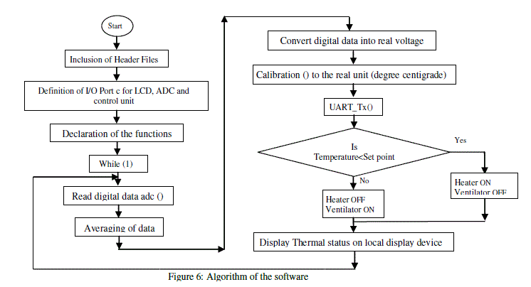
| The algorithm of the software designed for wireless sensor node, at a glance, is depicted through flow charts in figure 6. Along with main program, it sequentially executes following modules. |
| a. Analog to digital conversion [adc ()] |
| b. Calibration to the temperature [calibration ()] |
| c. Character display [lcd_display] |
| d. Decimal to BCD and ASCII conversion [(dec-bcd)] |
| e. Serial communication [UART()] |
| f. Configuration of LCD [LCD cmd ( )] |
| g. Sending data to LCD [LCD data( )] |
| h. Delay Function [Msdelay( ) ] |
| i. Thermal Control (S_onoff) |
| Thus, deploying embedded philosophy, the wireless sensor node, to detect and monitor thermal comfort, is designed along with the successful design of base station, wherein Zigbee based communication is realized. |
| The base station is associated with the coordinator node. As discussed earlier, the Zigbee module receives the data and with the help of its microcontroller section, it recognizes the node ID and distinguishes the data from node address. The data is communicated to PC through RS 232 port. Employing VB platform, the software is designed for base station to read and display data of respective domain in different windows. |
 |
V. RESULTS AND DISCUSSION |
| The wireless sensor nodes under investigation interact with the physical world, read the signal and process into real units. Hence, it is essential to calibrate the system to temperature scale. Therefore, the system is standardized, in the beginning, and then implemented for which it has been designed. |
| a) Calibration: The wireless sensor node under investigation is designed for monitoring of the thermal status of various domains of the polyhouse environment. To sense the temperature the precision temperature sensor, LM 35 is employed. It exhibits linear characteristics with (10mV/0C) as the scale factor. This signal is calibrated to the temperature scale. Following procedure is adopted for calibration. |
| Employing standard temperature bath the sensor of the present system is exposed to the temperature from 250C to 950C and temperature (t), dependent emf (VT) shown by the system are recorded. The temperature dependent emf VT is plotted against applied temperature (t) and depicted in figure 7. |
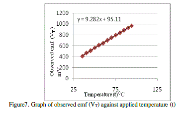 |
| From figure 7, it is found that, the system exhibit linear relationship with the process value (t). On standard regression process the empirical relation obtained is |
| VT= 9.282t + 95.11 … (3) |
| The offset of about 95.11 mV is observed, which may be due to analog component. However, the offset is compensated while employing the relation in embedded software. |
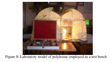 |
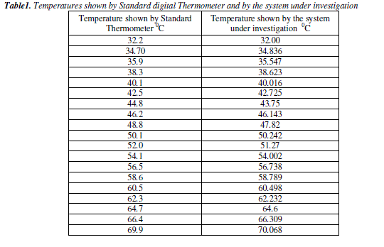
| To ensure real polyhouse environment, a model (figure 8) of polyhouse is designed in the laboratory for testing and standardization of the system. Incandescent lamps are used to heat the environment, whereas ventilating fans are deployed to provide proper ventilation. To confirm the calibration, the system installed in the polyhouse model whose environment is heated to the temperature up to 700C for the period of investigation. The temperature data shown by the system under investigation and that of obtained from the standard digital thermometer are presented in table 1. |
| On inspection of this table, it is found that, temperature shown by present system shows close agreement with that of observed from standard digital thermometer. This supports the reliability of the system development. |
 |
| b) Implementation: The objectives of the present work is to design, an innovative technology based sophisticated system to provide thermal comfort to the crops of polyhouse environment in spatio-temporal domain. Therefore, designed wireless sensor network is successfully implemented in actual polyhouse. The wireless sensor nodes are installed in the polyhouse at centre of respective domains of interest. Each domain is facilitated with the heating and ventilating arrangements whose actuation is controlled by respective nodes. The nodes are configured with set points. The wireless nodes, senses the thermal status and |
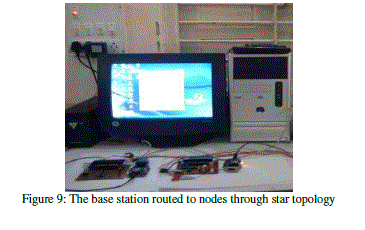 |
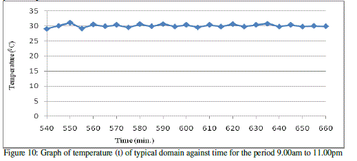
| communicates the same to base station, through wireless networking protocol (figure 9). The nodes are routed to base station in star topology of wireless communication. The temperatures, typically of 5 domains are continuously monitored. According to the predicted set points, both, heater as well as ventilators actuates and provides necessary thermal comfort to the crops. The observations are recorded for different period of the day. Figure 10 depicts the thermal status of the typical domain. On inspection of the figure 11, it can be said that, the temperature of domains almost remains constant with the hysteresis may be due to ON/OFF controlling method. Thus, present wireless sensor network system operates successfully and monitors the environment of the polyhouse very precisely. |
 |
VI. CONCLUSION |
| It can be concluded that the system works satisfactorily and helps to monitor and control thermal status of the environment of polyhouse very precisely. |