Keywords
|
| Fixed-width multiplier, Dual MIC, low-error, correction vector, input correction. |
INTRODUCTION
|
| The increase of portable communication and computing devices and the advance in mobile multimedia systems has made power consumption critical to optimize in the design of digital signal processing architectures Advances in VLSI technology have been a decisive factor in the growth of Digital Signal Processors (DSP), enabling the implementation of complex algorithms in portable systems. The energy challenge derived from scaling beyond submicron limits has modified the rules of digital design leading to new approaches to classic electronic design. The importance of energy and power efficiency in both, high performance and portable devices, and the need to reduce the energy expenditure in our current society are some of the main drivers that initiated this research. |
| Multipliers play a key role in the definition and design of Digital Signal Processing (DSP) systems. Not only are they a basic requirement in many algorithms, but they also shape and constrain precision, area and timing. On top of that, they are a main contributor in the overall power figures, hence the implementation of efficient parallel multipliers is desirable to achieve low-power arithmetic systems. Techniques that trade power consumption for system performance in multipliers are studied and compared in this thesis, with the main focus on the efficient implementation of DSP units by optimizing the power and accuracy performance of their multipliers. Truncated multipliers are thoroughly reviewed and com- pared to a novel proposed approach for adaptive power consumption where the power/accuracy operation point can be modified at run-time. Such a multiplier, the first approach to a column-based truncation control in the literature, is described, synthesized, simulated and tested in a customdesigned chip where the benefits of programmable truncation can be explored and are exploited in several typical arithmetic routines commonly used in signal processing units. |
| Fault-tolerant techniques are also studied from an energy efficiency point of view. The application of such techniques to the proposed DSP architecture shows, not only a combination of power reductions from both truncated multiplication and fault tolerance can be achieved, but the existence of synergies between both techniques to obtain further power reductions for DSP architectures. |
PROPOSED WORK
|
Baugh Wooley Algorithm
|
| Rather than do a subtraction operation, we can obtain the two’s compliment of the last two term and add all terms to get the final product the last two terms are n-1 bits each that extend in binary weight from position 2n-1 up to 22n-3.on the other hand, the final product is 2n bits and extends in binary weight from 20 up to 22n-1. We pad each of the last two terms with zeroes to obtain 2n-bit number to be able to add them to the other terms. The padded terms extend in binary weight from 20 up to 22n-1 Assuming x is one of the last two terms we can represent it with zero padding as |
 |
| The above equation gives the value of X due to the fact that a negative value is associated with the MSB. When we store X in a register, the negative sign at MSB is not used since X is stored as a binary pattern. The two’s compliment of x is obtained by complimenting all bits in the equations and adding ‘1’ at the LSB. The‘1’ pattern at MSB transforms into, |
 |
| Where overflow is ignored. Similarly, the ‘1’ pattern at position n-1 becomes |
 |
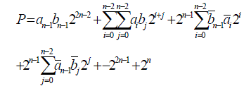
| The final product P=a x b becomes |
 |
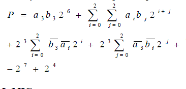
| Let us assume that a and b are 4-bit binary numbers, then the product p=a x b is 8-bits long and is given by |
 |
Error compensation Using DUAL MIC
|
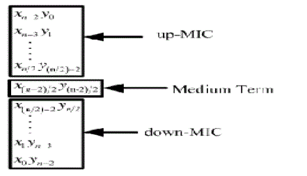
| We consider the impact of truncated products with the second most significant bits on the error compensation, but with lower hardware complexity. We propose a new error compensation circuit by using the dual group minor input correction (MIC) vector to further lower IC vector compensation error. By utilizing the symmetric property of MIC, fan-in can be reduced to half and hardware in up-MIC and down-MIC can be shared. Therefore, the hardware complexity of error compensation circuit can be lowered. Moreover, the hardware complexity just increases slightly as the multiplier input bits increase because we construct the proposed error compensation circuit mainly by the “outer” partial products. As compared with previous design, the proposed fixed-width multiplier not only performs with lower compensation error but also with lower hardware complexity, especially as multiplier input bits increase. |
| Baugh-Wooley array multiplier with two unsigned n-bit inputs of X and Y, which are shown as |
 (4) (4) |
| The multiplication result P is the summation of partial products of xi and yj, which is shown as |
 (5) (5) |
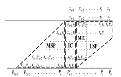
| The full-length n-bit unsigned Baugh-Wooley partial product array can be divided into three subsets of most significant part (MSP), IC vector and less significant part (LSP) as shown in Fig.1. To evaluate the accuracy of a fixed-width multiplier, we can exploit the difference between the n-bit fixed-width multiplier output and the 2n-bit full-length multiplier output, which is expressed as |
 (6) (6) |
| Where P is the output of the complete multiplier, and Pt is the output of the fixed-width multiplier. Pt can be expressed |
 (7) (7) |
 (8) (8) |
| Where f(IC) is the error compensation function. The error compensation function f(IC) is approximated as the sum of input correction vector with corresponding weight. To realize f(IC), the error compensation vector is divided into two disjoined sets and uses two addition trees to compute the error compensation. The error compensation algorithm is developed as |
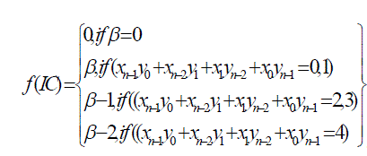 |
| Where β is the summation of all partial product terms in the input correction vector. |
| The first addition tree, which is devoted to lower weight partial products, is a standard one-counter constructed by using full adders and half adders. The lower weight partial products of IC include the most external four partial products, which are x5y0, x4y1,x1y4, and x0y5 in the 6-bit multiplier, having a weight of 2n in error compensation. |
| As for the second addition tree, it utilizes modified half-adders (mHAs) to take into account the contribution of partial products with higher weights. The higher weight partial products of IC include the other internal partial products, which are x3y2 and x2y3 in the 6-bit multiplier, having a weight of 2n-1 in error compensation. The difference between mHA and standard HA is that when inputs of A and B are both 1, sum=1 and Cout=1 in mHA instead of Sum=0 and Cout=1 in standard HA. |
Proposed Error Compensation Method
|
| The compensation errors can be divided into two categories: the first type is caused by insufficient error compensation, in which output Pt is smaller than ideal value P. In this case, ε = P-Pt> 0.On the other hand, the second type is due to over error compensation, in which output is larger than ideal value. In this case ε = P-Pt< 0. To consider both approximation error and circuit complexity, we mainly aim at dealing with the case of |ε|>2n-1in this paper. The weight of IC compensation circuit is 2n. We cannot correct all the cases of |ε|>2n-1 effectively if we only apply the partial product terms in IC to construct the error compensation function. Therefore, in this paper we adopt IC together with MIC, where MIC is the partial product vector with the most significant bits of LSP, to amend the error compensation value of f(IC). In this way, the cases of ε = P-Pt> 0 can be reduced effectively. |
| IC compensation circuit is constructed by dual IC compensation trees, which are the “inner” partial products with higher compensation weight and the “outer” partial products with lower compensation weight. According to the relation of IC and Savg (IC) in Table I, we can find out that the average compensation errors in the outer part and inner part are nearly the same, where the average compensation error is 0.0285 in the outer part and it is 0.0300 in the inner part. Here Savg (IC) is the average value of sum of the IC and LSP partial products. However, the number of partial product items with higher weight will increase with the number of bits, while the number of partial product items with lower weight is fixed. Therefore, we only analyze the error compensation tree with lower weight to find out the cases of |ε|>2n-1. Then we combine IC with MIC to adjust the function of f(IC) to make the compensation error lower than 2n- 1. |
| In this way, the error compensation circuit can be relatively simple and the compensation error can be lowered more efficiently. To find out a precise error correction vector, we analyze the sum of total errors in the cases of |ε|>2n- 1and |ε|<2n-1in under various β. In order to achieve an efficient error correction, we only amend the error compensation function f(IC) under the cases that the total error summation value of |ε|>2n-1 is larger than that of |ε|<2n-1. The analysis results are listed in Table II. By comparing the error summation value of |ε|>2n-1 with that of |ε|<2n-1in Table II, it can be observed that some under-compensated errors occur when β=2 and β=4. As a result, we combine IC with MIC to correct the under-compensated situations under the cases of β=2 and β=4. As for the case of β=1, there exists some over compensation errors. However, the total error summation value of |ε|>2n-1 is about the same with that of |ε|<2n-1. |
| We combine IC with MIC to correct the over compensation situations under the case of β=1 and SICh ≠0 instead of the case of β=1 only since in such case the error summation value of |ε|<2n-1 is much lower. Here SICh is the summation of IC that with higher weight, which can be written as |
 (10) (10) |
| The lower unit with the second most significant bits of truncated partial products is adopted as minor input correction (MIC) vector to reduce the compensation error, which is defined as TABLE I |
 |
Proposed Error Compensation Design Circuit
|
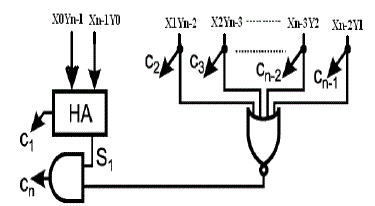
| The error compensation circuit we proposed is modified from the dual-tree design. To further reduce the compensation errors, we combine IC with MIC to correct the f(IC) under under-compensatedand over-compensated cases. The proposed design is illustrated in Fig. 2. The compensation function from C1 to Cn-2 is the same as fixedwidth multiplier. To reduce hardware complexity, the HA through C3to Cn-2 is removed. In the under compensation cases of β =2,4and over compensation case of β=1, we modify the compensation function in Cn-1 and Cn. The Boolean function of Cn-1 and Cn is expressed as |
 |
| Here SIC1is the summation of IC that with lower weight, ORICH is the OR result of all IC terms that with higher weight, NORICH is the NOR result of all MIC terms, and ORUP-MIC/ ORDOWN-MIC are the OR result of all up-MIC/down- MIC terms, respectively. |
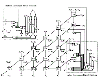
| In order to further reduce the circuit complexity, we apply De-Morgan’s law to simplify the proposed error compensation circuit in Cn-1 and Cn. After simplifying through DeMorgan’s law and hardware sharing, the transistor count in our proposed error compensation circuit can be reduced from 62 to 40. Finally, the Dual MIC fixed-width multiplier with error compensation circuit is illustrated in Fig. 2. |
Performance Comparisons
|
| In this section, we compare the proposed fixed-width multiplier with other literature designs to analyze their approximation error and hardware complexity, respectively. All performance comparisons are evaluated from 8-, 12-, to 16-bit. To analyze the compensation error, we inject all possible input patterns into the fixed-width multiplier. Then we compare the truncated output with their corresponding full-length multiplier output. By exploiting the difference between the n-bit fixed-width multiplier output and the 2n bit full-length multiplier output, we can obtain each error term. For truncation error comparison, we define the index of mean square error εms as |
 (13) (13) |
| The smaller value of εms represents the more precise error correction. The precision analysis results of various fixed-width multipliers are illustrated in Table III. In the previous literature designs, can perform the lower mean square errors because multiple-input error compensation vector designs are adopted in error correction. Especially in [8]–[10], they further take different weights of input correction partial products into account; as a result, the mean square errors can be lowered to 2.37% and 2.35% in the 16-bit fixed-width multiplier, respectively. In [6], the 2-D conditional estimation method can be more precise; however, their design is too complex. Similarly, a variable correction to include the more partial products columns of LSB part is proposed in [10] to enhance error compensation precision; however, the hardware complexity will increase accordingly. In our proposed design, we adopt the dualgroup MIC vector to further lower the compensation errors in [8] with lower hardware complexity. Most cases of |ε|>2n-1 in [8] can be removed; as a result, the mean square error is further lowered to 2.30% in the proposed 16-bit fixed-width multiplier. The comparison index of R% is defined as the transistor count of fixed-width multiplier divided by the transistor count of full-length multiplier, which can be defined as |
 |
| As illustrated in Table IV, the transistor count in the proposed design are more in the fixed-width multiplier with small width _ as compared with other literature designs [4], [7]–[10]. However, in the fixed-width multiplier with large width _, the transistor count in the proposed design are less as compared with literature designs in [4], [7]–[10]. To consolidate the comparison results in Tables III and IV, we compare the compensation error and transistor count together in Fig. 6. As illustrated in Fig. 6, the proposed design performs the lowest mean square error; moreover, its transistor count can be lower than the design in [7]–[10] in the 16-bit fixed-width multiplier. In general, to achieve lower compensation error needs more complex compensation algorithm and more complicated circuit hardware. In this paper, we combine IC with MIC to adjust the function of f(IC) to lower the compensation error. We also analyze the error compensation tree only with lower weight to find out the cases of ε|>2n-1 in our proposed design. Therefore, circuit complexity in the most error compensation circuit is fixed, which will not increase along with input bit number. |
| As a result, the error compensation circuit can be relatively simple, especially as the input bit number increases. As illustrated in Fig. 7, the slope of transistor count increasing as the fixed-width multiplier input number increases is gentler in our proposed design. Though in our proposed design we must spend more transistor count in the 8-bit fixed-width multiplier, we spend less transistor count in the cases of input bit number are larger than eight. The superiority in area-efficiency in our design is more obvious as input number increases. Finally, we implement the proposed 16-bit low-error, area-efficient fixed-width multiplier in TSMC 0.18-μm process as illustrated in Fig. 8. The silicon chip area of the proposed fixed-width multiplier circuit is 109.8 μm by 106.8 μm. As compared with [8], the critical paths in both our design and [8] are located in the path of propagation. In both designs the circuit delay are nearly the same under various timing constraints, which all are faster than the conventional ripple designs. The circuit layout area and power consumption in the proposed design is slightly lower than that of [8] since lower transistor count and less wire connection in the error compensation circuit even though our design is more irregular |
SOFTWARE REQUIREMENT
|
MODELSIM 6.3f
|
| ModelSim is an easy-to-use yet versatile VHDL/ (System) Verilog/SystemC simulator by Mentor Graphics. It supports behavioral, register transfer level, and gate-level modeling. ModelSim supports all platforms used here at the Institute of Digital and Computer Systems (i.e. Linux, Solaris and Windows) and many others too. On Linux and Solaris platforms ModelSim can be found preinstalled on Institute's computers. Windows users, however, must install it by themself. It introduces you with the basic flow how to set up ModelSim simulator, compile your designs and the simulation basics with ModelSim SE. The example used in this tutorial is a small design written in VHDL and only the most basic commands will be covered in this tutorial. This tutorial was made by using version 6.3f of ModelSim SE on Linux. |
CONCLUSION
|
| In conclusion, a low-error and efficient area fixed-width multiplier by using the dual group minor input correction vector is presented. As compared with the previous error compensation circuit, the proposed fixed-width multiplier performs not only with lower compensation error but also with lower hardware complexity, especially as multiplier input bits increase. The proposed 16-bit fixed-width multiplier circuit is implemented in TSMC 0.18-μm process and the silicon area is 11726.64 μm2. The mean square error in the proposed design is lowered to 2.30%. The transistor counts in the proposed design are only 53% of the full-length multiplier. The power consumption is lowered to 7.2%. |
Tables at a glance
|
 |
 |
 |
 |
| Table 1 |
Table 2 |
Table 3 |
Table 4 |
|
Figures at a glance
|
 |
 |
 |
 |
| Figure 1 |
Figure 2 |
Figure 3 |
Figure 4 |
|
References
|
- Y. C. Lim, “Single-precision multiplier with reduced circuit complexity for signal processing applications,” IEEE Trans. Comput., vol. 41, no. 10, pp. 1333–1336, Oct. 1992.
- M. J. Schulte and E. E. Swartzlander, Jr., “Truncated multiplication with correction constant,” in Proc. Workshop VLSI Signal Process., 1993, vol. VI, pp. 388–396.
- S. S. Kidambi, F. El-Guibaly, and A. Antoniou, “Area-efficient multipliers for digital signal processing applications,” IEEE Trans. Circuits Syst.II, Exp. Briefs, vol. 43, no. 2, pp. 90–95, Feb. 1996.
- J. M. Jou, S. R. Kuang, and R. D. Chen, “Design of low-error fixed width multipliers for DSP applications,” IEEE Trans. Circuits Syst. II, Exp.Briefs, vol. 46, no. 6, pp. 836–842, Jun. 1999.
- S. J. Jou and H. H.Wang, “Fixed-width multiplier for DSP application,” in Proc. IEEE Int. Symp. Comput. Design, 2000, pp. 318–322.
- Y. C. Liao, H. C. Chang, and C. W. Liu, “Carry estimation for two’s complement fixed-width multipliers,” in Proc. Workshop Signal Process.Syst., 2006, pp. 345–350.
- F. Curticapean and J. Niittylahti, “A hardware efficient direct digital frequency synthesizer,” in Proc. IEEE Int. Conf. Electron., Circuits, Syst., 2001, vol. 1, pp. 51–54.
- A. G. M. Strollo, N. Petra, and D. D. Caro, “Dual-tree error compensation for high performance fixed-width multipliers,” IEEE Trans. CircuitsSyst. II, Exp. Briefs, vol. 52, no. 8, pp. 501–507, Aug. 2005.
- S. R. Kuang and J. P. Wang, “Low-error configurable truncated multipliers for multiply-accumulate applications,” Electron. Lett., vol. 42, no. 16, pp. 904–905, Aug. 2006.
- N. Petra, D. D. Caro, V. Garofalo, N. Napoli, and A. G. M. Strollo, “Truncated binary multipliers with variable correction and minimum mean square error,” IEEE Trans. Circuits Syst. I, Reg. Papers, vol. 57, no. 6, pp. 1312 1325, Jun. 2010
- Jiun-Ping Wang, Shiann-RongKuang, Member, IEEE, and Shish-Chang Liang, “High-Accuracy Fixed-Width Modified Booth Multipliers for Lossy Applications”, IEEE transactions on very large scale integration (VLSI) systems, vol. 19, no. 1, January 2011.
- I-Chyn Wey and Chun-Chien Wang “Low-Error and Hardware-Efficient Fixed-Width Multiplier by Using the Dual-Group Minor Input Correction Vector to Lower Input Correction Vector Compensation Error” IEEE transactions on very large scale integration (VLSI) systems, vol. 20, no. 10, October 2012.
|