ISSN ONLINE(2320-9801) PRINT (2320-9798)
ISSN ONLINE(2320-9801) PRINT (2320-9798)
K.Jayalakshmi1, B.Sivasankari2
|
| Related article at Pubmed, Scholar Google |
Visit for more related articles at International Journal of Innovative Research in Computer and Communication Engineering
An error detection method for EG-LDPC codes with majority logic decoding is presented in this paper. Majority logic decodable codes are suitable for memory applications due to their capability to correct a large number of errors. They are simple to implement and have modular encoder and decoder. However, they require a large decoding time that impacts memory applications. Mostly memory applications require low latency encoders and decoders. So the proposed method has reduced a decoding time by detecting whether a word has errors in the first iteration of majority logic decoding and when there are no errors in the decoding ends without completing the rest of the iterations. Since most words in a memory will be error free, so the average decoding time is greatly reduced compared to existing methods
I. INTRODUCTION |
| The continuous impact of technology scaling has been affecting the reliability of memory applications not only in extreme radiation environments like spacecraft and avionics electronics, but also at normal terrestrial environments. Especially, SRAM memory failure rates are increasing significantly, therefore posing a major reliability concern for many applications[1]. Memory cells are mainly susceptible from soft or transient errors. |
| For reliable performance those faults can be detected using Error Correction Codes (ECC). When digital data is stored in a memory, it is crucial to have a mechanism that can detect and correct a certain number of errors. ECC encodes data in such a way that a decoder can identify and correct certain errors in the data. Usually data strings are encoded by adding a number of redundant bits to them. When the original data is reconstructed a decoder examines the encoded message, to check for any errors[8]. |
| 1.1 Error Correction Codes (ECC) |
| There are 2 basic types of Error Correction Codes: |
| 1.Block codes,: This codes are referred to as (n,k) codes. |
| 2.Convolution codes: The code words produced depend on both the data message and a given number of previously encoded messages. |
| Among the ECC codes that meet the requirements of higher error correction capability and low decoding complexity, cyclic block codes have been identified as good one, due to their property of being Majority Logic (ML) de codable. LDPC (Low Density Parity Check) codes belong to the family of ML de codable codes. Euclidean Geometry Low Density Parity check Codes (EG-LDPC) are one step ML de codable codes with high error correction capability and are linear cyclic block codes[2]. |
| 1.2 EG-LDPC: |
| Euclidean Geometry codes are also called EG-LDPC codes based on the fact that they are low-density parity-check (LDPC) codes.LDPC codes have a limited number of 1’s in each row and column of the matrix; this limit guarantees limited complexity in their associated detectors and correctors making them fast and light weight[3]. |
| EG-LDPC has the following parameters for any positive integer t ≥2 |
| • Information bits, k=22t – 3t |
| • Length, n =22t – 1 |
| • Minimum distance, d min =2 t +1 |
| • Dimensions of the parity-check matrix, n x n |
| • Row weight of the parity-check matrix, p =2t |
| • Column weight of the parity-check matrix, y =2t |
II. CODING SCHEME |
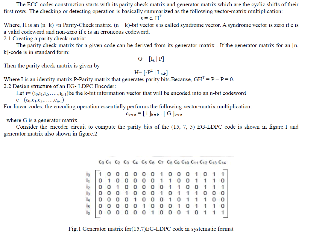 |
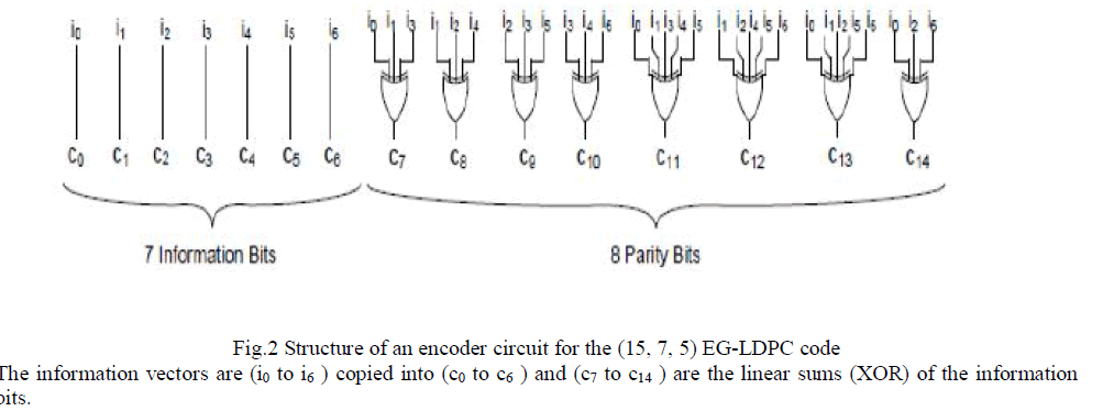 |
III. EXISTING MAJORITY LOGIC DECODER (MLD) |
| MLD is based on a number of parity check equations which are orthogonal to each other.so that, at each iteration, each code word bit only participates in one parity check equation, except the very first bit which contributes to all equations. For this reason, the majority result of these parity check equations decide the correctness of the current bit under decoding. ML decoder is a simple and powerful decoder, capable of correcting multiple random bit-flips depending on the number of parity check equations. |
| 3.1 Plain ML Decoder |
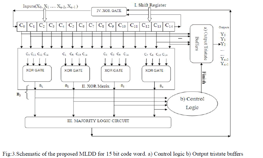
| As described before, the ML decoder is a simple and powerful decoder, capable of correcting multiple random bit-flips depending on the number of parity check equations. It consists of four parts: 1) a cyclic shift register; 2) an XOR matrix; 3) a majority gate; and 4) an XOR for correcting the codeword bit under decoding. The input signal is initially stored into the cyclic shift register and shifted through all the taps. The intermediate values in each tap are then used to calculate the results {Bj} of the check sum equations from the XOR matrix. In the Nth cycle, the result has reached the final tap, producing the output signal (which is the decoded version of input) [1]. |
| 3.2 Plain MLD With Syndrome Fault Detector (SFD) |
| In order to improve the decoder performance, alternative designs may be used. One possibility is to add a fault detector by calculating the syndrome, so that only faulty code words are decoded [4]. Since most of the code words will be error-free, no further correction will be needed, and therefore performance will not be affected. Although the implementation of an SFD reduces the average latency of the decoding process, it also adds complexity to the design. |
IV. PROPOSED ML DETECTOR / DECODER |
| In the proposed Majority Logic Detector/Decoder (MLDD), the data words are encoded using EG-LDPC and then stored in the memory. When the memory is read, the code word is then fed through the ML detector/decoder before sent to the output for further processing. In this decoding process, the data word is corrected from all bit-flips that it might have suffered while being stored in the memory. |
| 4.1. Hypothesis: |
| The proposed technique is based on the following hypothesis: “Given a word read from a memory protected with EG-LDPC codes, and affected by up to four bit-flips, all errors can be detected in only three decoding cycles.”[2] |
| 4.2.MLDD design: |
| The figure 3 shows the proposed ML detector/decoder with 15-tap shift register and an XOR array to calculate the orthogonal parity check sums.A majority gate for deciding if the current bit under decoding needs to be inverted. The control unit triggers a finish flag when no errors are detected after the third cycle. The output tristate buffers are always in high impedance unless the control unit sends the finish signal so that the current values of the shift register are forwarded to the output y. |
 |
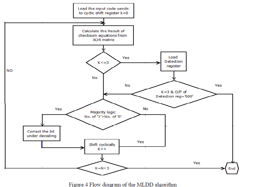
| The Proposed MLDD algorithm is illustrated in Fig.4.Proposed MLDD algorithm requires additional logic compared to the MLD algorithm. The corrections are performed during the first N iterations If the majority gate detect any error in codeword the iterations take place depends upon the length of the codeword’s. |
 |
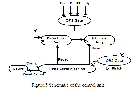
| An additional logic unit of proposed MLDD is control and tristate buffer logic which shown in figure.5The control unit manages the detection process. It uses a counter that counts up to three, which distinguishes the first three iterations of the ML decoding. |
 |
| Data bits stay in memory for a number of cycles and, during this period, each memory bit can be upset by a transient fault with certain probability. Therefore, transient errors accumulate in the memory words over time. In order to avoid accumulation of too many errors in any memory word that surpasses the code correction capability, the system must perform memory scrubbing. Memory scrubbing is the process of periodically reading memory words from the memory, correcting any potential errors, and writing them back into the memory. |
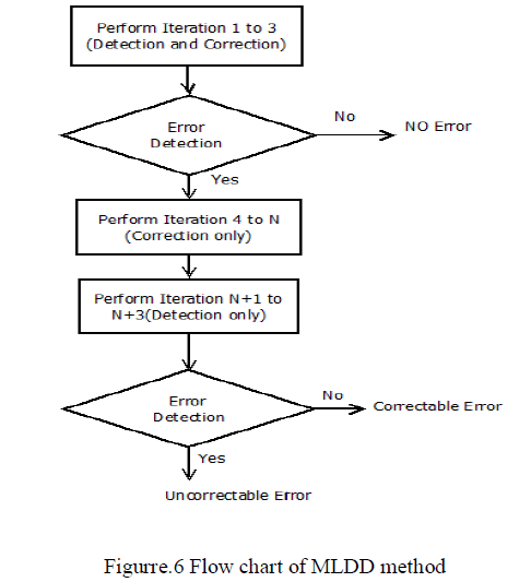 |
| The flow chart for MLDD method as shown in Fig.6. Iteration from 1 to 3 will be performed for detection of the error in the codeword. If the codeword is error free then output will be obtained in three iteration. Otherwise iteration is continued to detect and correct the error in the codeword. Iteration from 4 to N will be preformed to correct the error in the codeword. Performances N+1 to N+3 iteration are to detect the error in codeword. If the error is detected then it will corrected. Otherwise retransmission will be processed. |
| Since we are using a separate module for fault detection, there will be a slight area overhead. This area overhead can be overcome by using sorting network in the majority gate. The EG LDPC code used here is only for 15 bits, it have only outputs four outputs from xor matrix. It takes only four input bits and the vertical lines shown here is comparator as shown in Figure 7 (b) which has two inputs and it will compare and larger bit is given to the top output and smaller to bottom respectively [3]. |
 |
V. CONCLUSION |
| For the plain MLD, the memory read access delay is directly dependent on the code size(in this case a code with length 15 needs 15 cycles etc.) Then, for I/O two extra cycles needed. On the other hand, for proposed MLDD the memory read access delay is only dependent on the word error rate (WER). The proposed design just requires three cycles to detect any error (plus two of I/O). If an error is detected, all of the techniques need to run the whole decoding process.The proposed MLDD also have same procedure, but instead of N+2 cycles, three extra cycles are needed (for a total of N+2) is summerised in table I. |
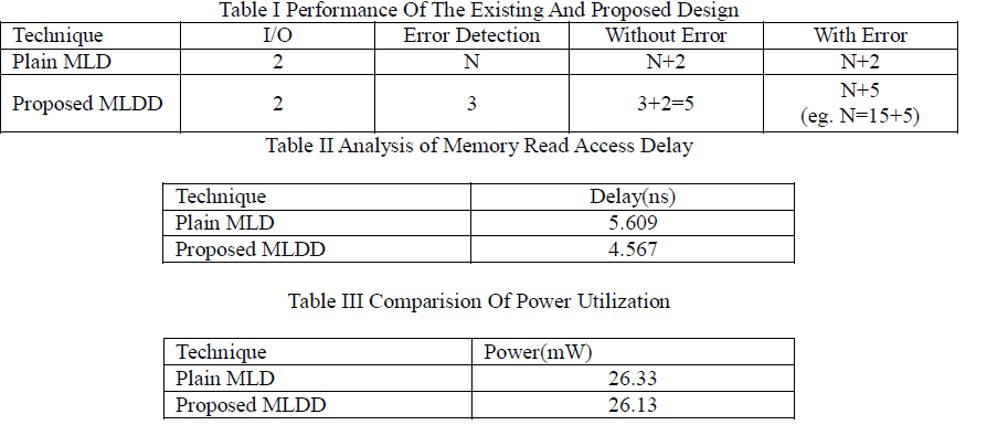 |
| The Proposed MLDD have less delay when compared to existing MLD, since the proposed dessign detects the faults in just three cycles. The delay comparison is shown in table II.When the code word does not suffer from errors, it can come out in the next 4th cycle itself without further shifting. Therefore this is a great advantage for MLDD in terms of delay and performance. |
VI. FUTURE WORK |
| The further scope is to eliminate the silent error corruption. If the input has more than four bit error in the codeword, then the MLDD process is not exactly suitable to correct the codeword. In such case, silent fault corruption may occur. To reduce such fault, one more detection logic can be implemented after the completion of 15 iteration. The applications of the proposed techniques to memories that use scrubbing is also an interesting topic and was in fact the original motivation that led to the Parallel MLDD scheme. |
References |
|