ISSN ONLINE(2278-8875) PRINT (2320-3765)
ISSN ONLINE(2278-8875) PRINT (2320-3765)
| M V Giridhar1 Talati Dhruvesh2 A GouthamVenkata Sai3 K Anil Kumar4 K Guna Sekhar5 Dept. of EEE, KL University, Vaddeswaram, Guntur, A.P., India |
| Related article at Pubmed, Scholar Google |
Visit for more related articles at International Journal of Advanced Research in Electrical, Electronics and Instrumentation Engineering
Space Vector Modulation (SVM) Technique has become the most popular and important PWM technique for three phase Voltage Source Inverters for the control of AC Induction, Brushless DC, Switched Reluctance and Permanent Magnet Synchronous Motors. Z-Source Inverters have the ability to boost the dc link voltage, thus increasing the output ac voltage beyond the values reached by conventional inverters. The enhanced ratio from ac output voltage to dc link voltage is possible due to an impedance network connected between the dc power supply and the main converter. In this paper space vector is implemented for z source inverter and brushless dc motor is fed by zsource inverter. The simulation results are supported with SIMULINK.
Keywords |
| z-source, space vector, low harmonics, bldc |
INTRODUCTION |
| Voltage Source Inverters (VSI) controlled by Space Vector Modulators (SVM) produce output voltages whose fundamental amplitude is given by[1] |
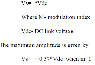 |
| On the other hand, Z-Source Inverters (ZSI) produce output voltages that are higher than those obtained by the Voltage source inverter |
| Vzs,max>Vs,max |
| with the same VDc. This is the main advantage of this configuration. |
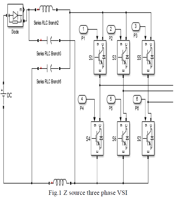
| The intermediate circuit of the ZSI is composed by two inductors, L z, two capacitors , and a diode D z, see Fig. 2. Assuming that both inductors have the same inductance, and both capacitors have the same capacitance, the order of the differential equations can be reduced in two. The state variables of the intermediate circuit are iz and v z. The inverter is a two-level VSI formed by six IGBTs. The load is a three phase RL circuit. |
 |
SPACE VECTOR PULSE WIDTH MODULATION |
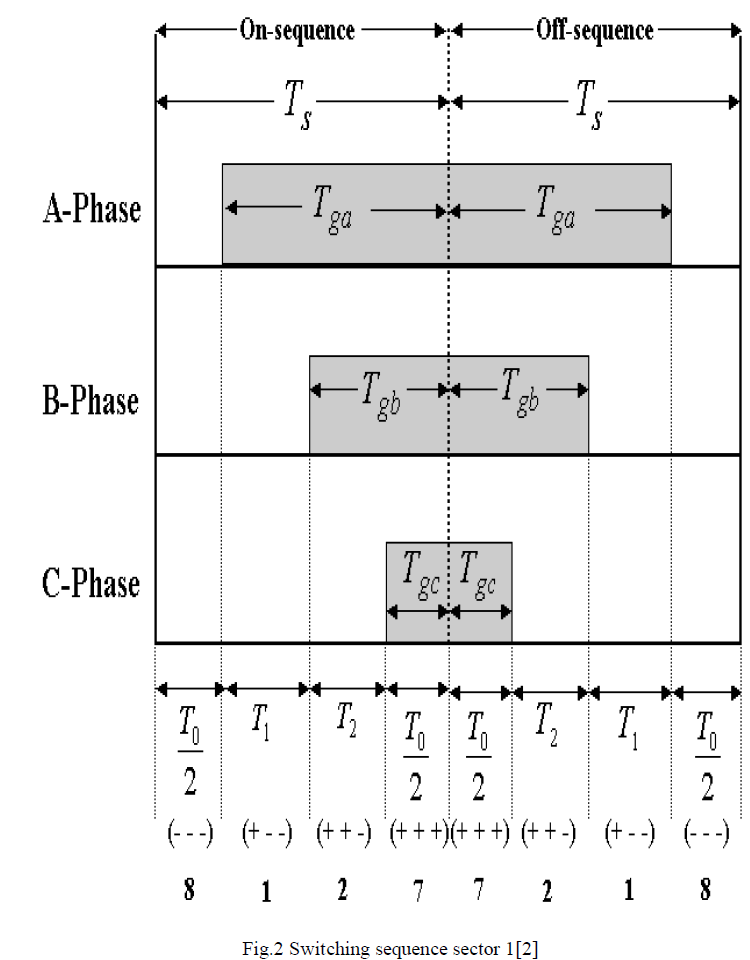
| Space vector modulation is a PWM control algorithm for multi-phase AC generation, in which the reference signal is sampled regularly; after each sample, non-zero active switching vectors adjacent to the reference vector and one or more of the zero switching vectors are selected for the appropriate fraction of the sampling period in order to synthesize the reference signal as the average of the used vectors. The topology of a three-leg voltage source inverter is Because of the constraint that the input lines must never be shorted and the output current must always be continuous a voltage source inverter can assume only eight distinct topologies. Six out of these eight topologies produce a nonzero output voltage and are known as non-zero switching states and the remaining two topologies produce zero output voltage and are known as zero switching states. |
| The space vector modulation (SVM) technique is more popular than conventional technique because of the following excellent features: |
| It achieves the wide linear modulation range associated with PWM third harmonic injection automatically. |
| It has lower base band harmonics than regular PWM or other sine based modulation methods, or otherwise optimizes harmonics. |
| 15% more output voltage then conventional modulation, i.e. better DC-link utilization. |
| More efficient use of DC supply voltage. |
| SVM increases the output capability of SPWM without distorting line-line output voltage waveform. |
| Advanced and computation intensive PWM technique. |
| Higher efficiency. |
| Prevent un-necessary switching hence less commutation losses. |
| A different approach to PWM modulation based on space vector representation of the voltages in the α-β plane. |
STEPS TO IMPLEMENT SVPWM: |
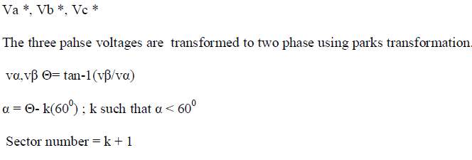
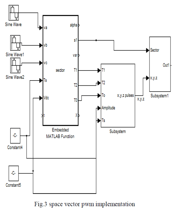
| 1) The sector in which the tip of the reference sector is situated is to be determined from the instantaneous phase references Va *, Vb * and Vc* |
 |
| 2) Computation of T1 and T2; here lookup tables are needed to know the values of Sin (60°- α) and Sin α |
| 3) Determination of switching vectors. |
| Using the corresponding sector information the actual switching time for each inverter leg is generated from the combination of effective times and zero sequence time. Equating volt-seconds along the α -axis: |
| (ÃÂÃâ VsrÃÂÃâ cosα)* Ts = Vdc *T1 + (Vdccos600) * Ts |
| Equating volt-seconds along the β -axis: |
| (ÃÂÃâ VsrÃÂÃâ sinα) * Ts = (Vdcsin60°) *T2 |
| Solving the above two simultaneous equations, one gets: |
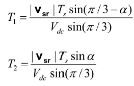 |
| |Vsr | represents the length of the reference Vector and is measured from the start of the vector. |
| 4) Assert the appropriate control signals to affect the required switching action. |
 |
 |
MODELLING OF BLDC MOTOR |
| The modelling is carried based on assumptions that |
| the induced currents in the rotor due to stator harmonics are neglected. |
| Iron and stray losses are also neglected. |
| Motor modelling is done based on derivations provided in[3] |
| The stator voltage equations in terms of electrical constants are |
| = + p + |
| Where Rs - Rotor resistance |
| La, Lb, Lc – Self inductance of each phase windings |
| Lm – Mutual inductance |
| ias, ibs, ics – Currents in stator windings |
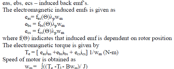 |
| Where wm – rotor speed in mechanical rad/s |
| B – friction coefficient |
| J – Inertia of motor shaft |
SIMULATION RESULTS |
 |
 |
 |
 |
CONCLUSION |
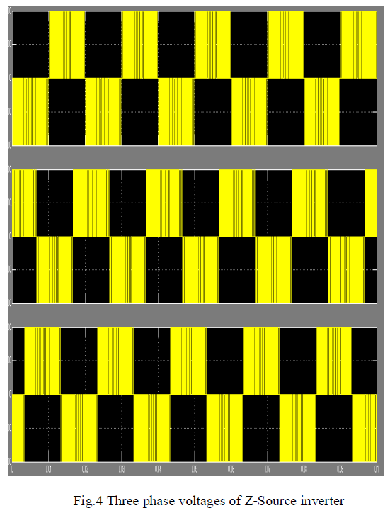
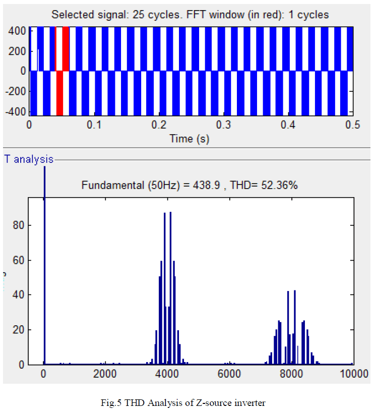
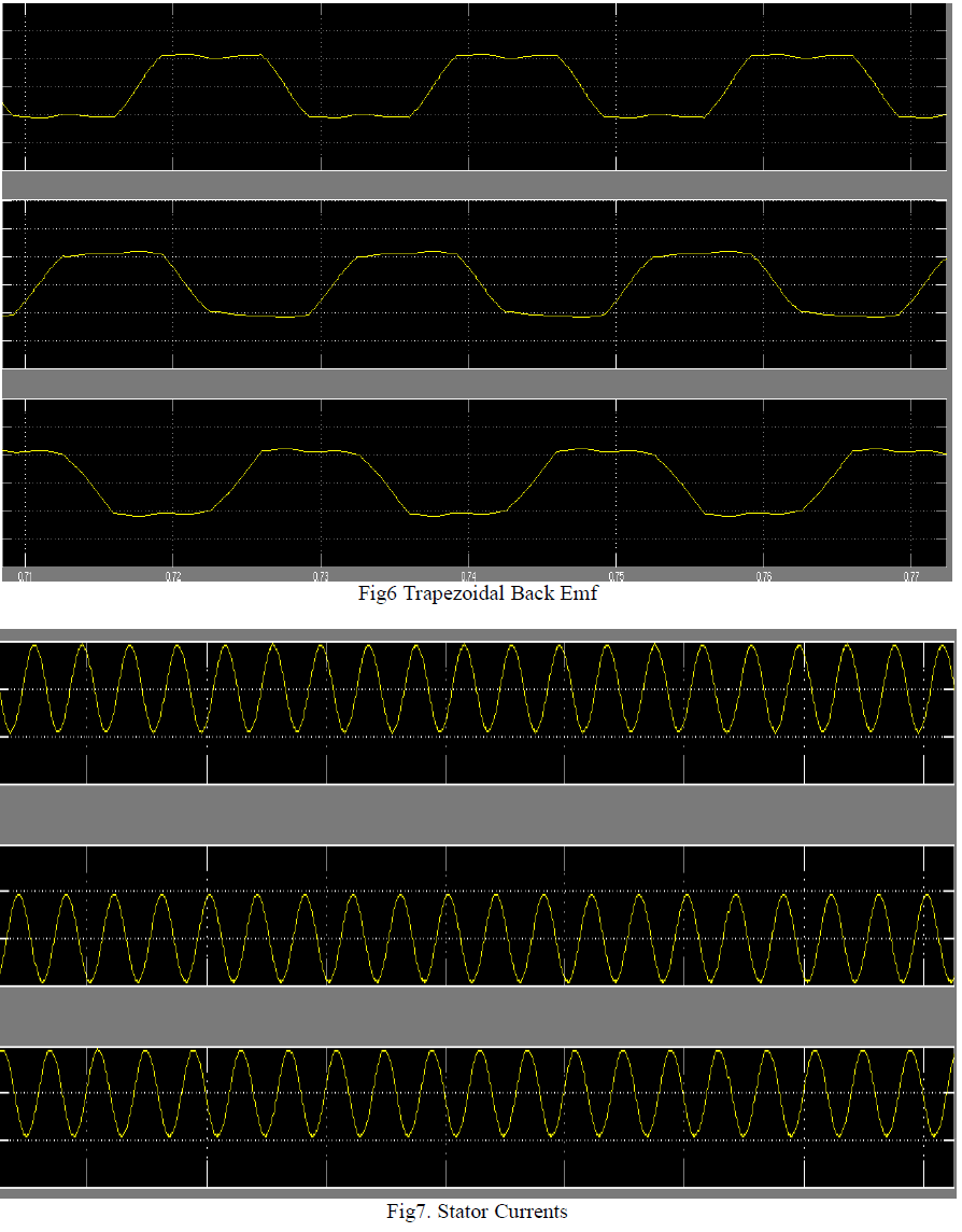
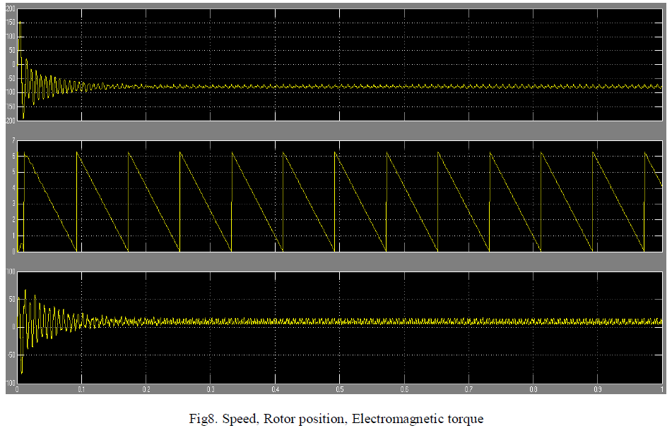
| The z source inverter produces more output voltage than conventional voltage source inverters the same is observed in this paper. Space vector pwm is implemented for zsource inverter.The brushless dc motor is fed by z source inverter. The performance characteristics of brushless dc motor like trapezoidal emf, electromagnetic torque, speed, rotor position are obtained. |
References |
|