Keywords
|
| Cascaded MLI, PWM, PD, POD, APOD, THD, RMS. |
INTRODUCTION
|
| An effective and practical solution to reduce harmonics and to meet the increasing power demand is the multilevel inverter. The most common MLI topologies classified into three types are diode clamped MLI, flying capacitor MLI, and cascaded H-Bridge MLI. The hybrid and asymmetric hybrid inverter topologies have been developed according to the combination of existing MLI topologies or applying different DC bus levels respectively [5]. The 3-level diode clamped inverters, mostly a good solution for motor drive applications besides other multilevel inverter topologies. However, it would be a limitation of complexity and number of clamping diodes for the diode clamped MLIs, when the level exceeds three. The Flying Capacitor-MLIs are based on balancing capacitors instead of diodes and generate multilevel output voltage waveform by capacitor clamping. To increase the number of output levels it requires more number of capacitor thus increasing the complexity of considering DC-link balancing. Among the three types of multilevel inverters, the cascade inverter has the least components for a given number of levels [3]. The cascade inverters also allow using various pulse width modulation (PWM) strategies to control the inverter accurately .A high magnitude sinusoidal voltage with extremely low distortion at fundamental frequency can be produced by connecting the number of DC levels using progressive methods. In this paper Quasi Hybrid Cascaded Multilevel Inverter (QHCMLI) is developed using various pulse width modulation (PWM) strategies. |
RELATED WORK
|
| Cascaded type of MLI has the least components for [9] the number of levels selected than the other types of MLI. Hbridges connected in series can be excited by several separate DC sources which may be fuel cell or PV cell. This leads to the applications of MLI in the interface of renewable energy sources and also in applications including inductions machine and motor drives, active rectifiers, filters, flexible AC transmission systems and static compensators. The cascaded MLI allows various pulse width modulation strategies [4] including selective harmonic elimination PWM (SHE-PWM), sinusoidal PWM (SPWM), space vector PWM (SVPWM) etc., The SPWM control method is very popular as it reduces the distortion harmonics by using several level shifting options on carrier signal. In SPWM a sinusoidal reference voltage waveform is compared with a triangular wave form to generate switching gate signals for the MLI [1]. The stepped sine PWM using several multicarrier signals [7] can also generate the pwm switching strategy for the harmonic reduction. The binary mode of selecting the dc supply for each H-bridge can be used by the MLI to increase the number of output levels to reduce the THD [6]. Binary type MLI with four H-bridges connected in series can generate ac sine output with thirty one levels whereas for the same 4 H-bridges using equal dc sources can output up to 9 levels. In this paper dc link sources for the four H-bridges connected in series use quasi method and it generates up to 55 levels of MLI output. The advantage of quasi method is the achievement of higher number of output levels without increasing the number of H-bridges. |
QUASI HYBRID MLI
|
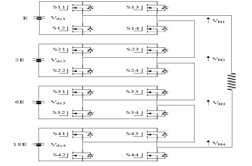
| Fig. 1 shows the schematic of Quasi Hybrid Cascaded Multilevel Inverter (QHCMLI). QHCMLI consists of four H-bridges connected in series with separate dc sources. The ratio of dc sources selected for each H-bridge can be expressed as |
 (1) (1) |
| E is considered as the unit DC link voltage and Vdci represents the DC link voltage of the ith H-Bridges. In a four-HBs single phase |
 (2) (2) |
| It consists of 8 active switching states to make the output voltage depending on the switching condition of the switches. The output voltage of the ith H-Bridge is |
 (3) (3) |
| Fi is the switching function. The value of Fi is 1 or -1 or 0. Table I shows the relationship of the Fi, VHi and states of switches. For the value 1, switches Si1 and Si4 are turned on and for zero, the switches Si1 and Si3 or Si2 and Si4 need to be turned on. Similarly for the value -1, switches Si2 and Si3 are turned on |
BIPOLAR MODULATION CONTROL SCHEMES
|
| In general multicarrier based PWM strategies single bipolar with sinusoidal reference are used in MLI to produce switching patterns. The bipolar controlled sine signal is compared with fixed amplitude fixed/variable frequency triangular carrier signal. The number of carrier signals required to produce m level output is (m-1). The entire carriers having the fixed amplitude and fixed frequency are termed as (FAFF) and fixed amplitude and variable frequency as (FAVF). The reference signal is continuously compared with the carrier signal and whenever the reference signal is greater than carrier signal transient occurs from zero to one and otherwise one to zero is generated to form PWM. |
 (4) (4) |
| The frequency modulation index is where mf is the frequency modulation, fc is the carrier signal and fr is the reference signal. The amplitude modulation for Phase Disposition (PD), Phase Opposition Disposition (POD) and Alternative Phase Opposition Disposition (APOD) is |
 (5) (5) |
| Where ma represents the amplitude modulation Ar is the reference amplitude and Ac is the carrier amplitude. The PWM strategies are developed using MATLAB/SIMULINK. In this paper hybrid cascaded type MLI using quasi mode for dc source selection is used to generate 55-level ac output. |
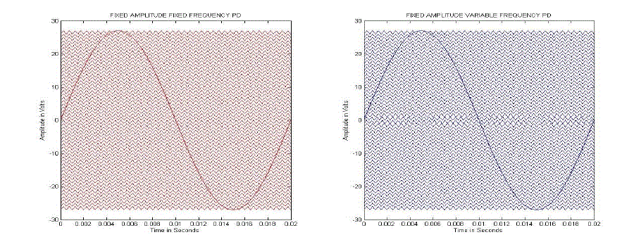
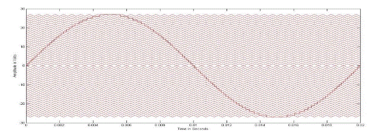
| The number of carrier signals used is 54 with 27 carriers on the positive side and 27 carriers on the negative side. A sinusoidal reference signals with different ma is used to generate the switching patters for QHCMLI. Fig. 2 shows the generated reference signal with FAFF and FAVF 54 number of carriers arranged in-phase at different dc levels called as PD PWM method. |
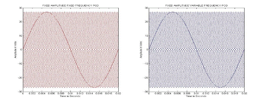
| Fig. 3 shows the phase opposition disposition (POD) PWM methods where the carriers are arranged in–phase and out of phase above and below the zero line. |
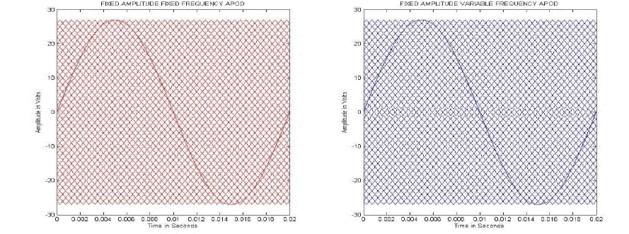
| Fig. 4 shows the APOD PWM method where the alternate carriers are in phase and adjacent carriers are out of phase. Sinusoidal reference is selected in the above Fig. 2, 3, & 4. |
Proposed Bipolar Modulation Control Scheme
|
| Stepped sine wave is used as reference instead of pure sine wave. Stepped angles to generate the proposed reference are calculated by switching angle method. There are different switching angle methods say Equal Phase method (EPM), Half Equal Phase Method (HWPM), Half Height Method (HHM) and Feed Forward Method (FFM). |
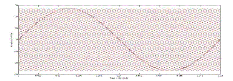
| Out of the above mentioned methods, half height method is selected for generating stepped sine reference because the other methods do not generate sine shaped reference. When the function value increases to the half-height of the level, the switch angle is set and thus better output waveform obtained. The main switching angles α1, α2..... αm are determined where m represents the number of levels. Fig. 5, 6 & 7 shows the proposed stepped sine reference signal compared with multicarrier signal using FFFAPDPWM, FFFAPODPWM and FFFAAPODPWM strategies. |
RESULT AND DISCUSSION
|
| Fig. 8 shows the 55 level output of QHCMLI using FAFF and FAVF carrier signals and sine wave reference under PD, POD and APOD PWM methods. In the Fig. 8 (b) and (c) the MLI output using FAFF carrier experiences zero shift error. Zero shift error is a non-zero amplitude value at t=0.01ms for a period of 0.02ms sine output. Zero shift error can be eliminated by using FAVF carrier signals. Zero shift error occurs in FAFF POD and APOD PWM method. |
| Fig. 9 & 10 shows the sine and stepped sine reference based 55 levels output voltage of QHCMLI PD, POD and APOD. |
| Fig. 11 & 12 represents the FFT analysis of sine and stepped sine reference based PD, POD and APOD. |
| Table II shows the analysis of 55 levels QHCMLI for reduction in harmonics and DC bus utilization using the performance indices say THD, VRMS, crest factor, form factor, Distortion factor. The performance measures are carried out for different amplitude modulations ranging from 0.97 to 1.00 using different PWM methods. The performance evaluations are also carried out with carriers under FAFF and FAVF. Carriers with FAVF are designed to enhance exact zero crossing of the sinusoidal AC output at the middle value of the time period. Usage of FAVF carriers in POD and APOD shows good improvement in the symmetric property of the MLI output over the MLI outputs shown in Fig.8.Table II highlights the better performance of the proposed method for maximum ma and the elimination of zero– crossing error with FAFF carriers in POD and APOD PWM methods. |
| Table III indicates the achievement of reduced THD by more than 65% with the proposed PWM strategy when compared with FAFF and FAVF carriers using sine referenced 55 levels QHCMLI. It also shows the high voltage output rms value say 189.8V for less THD value 1.46% hence satisfying the needs of applications requiring both the criteria of reduced THD and good DC bus utilisation. |
CONCLUSION
|
| Table II and III shows that 55 level QHCMLI with ma = 1 using the proposed switch patterns could perform satisfactorily for the applications requiring reduction of THD and good dc bus utilisation. The obtained results also show the achievement of higher number of output levels with less number of H-bridges. The increase in the number of output levels decreases the THD. |
| |
Tables at a glance
|
|
|
| |
Figures at a glance
|
 |
 |
 |
 |
 |
| Figure 1 |
Figure 2 |
Figure 3 |
Figure 4 |
Figure 5 |
| |
 |
 |
 |
 |
 |
| Figure 6 |
Figure 7 |
Figure 8 |
Figure 9 |
Figure 10 |
| |
 |
 |
| Figure 11 |
Figure 12 |
|
| |
References
|
- B.P. McGranth and Holmes, “Multicarrier PWM strategies for multilevel inverter“, IEEE Tras.Ind.Electron, Vol.49, no.4, pp.858-867,Aug2002.
- F. S. Kang, S. J. Park, C. U. Kim and T. Ise, “Multilevel PWM inverters suitable for the use of stand-alone photovoltaic power system”, IEEETrans. Energy Conversion, Vol. 20, no. 4, pp.906-915, 2005.
- Yu Lin and Fang Lin Luo, “Trinary hybrid 81 level multilevel inverter for motor drive with zero common mode voltage”, IEEE Conference inproceedings, pp1-7, 2007.
- Z. Jinghua and L. Zhengri, “Research on hybrid modulation strategies based on general hybrid topology of Multilevel inverters”, proceedingsIEEE SPEEDAM International symposium on power electronics, electric drives, automation and motions Italy 2008.
- P. Lezana, J. Rodriguez and D.A. Oyarzu,, “Cascade multilevel inverter with regeneration capability and reduced number of switches”, IEEETrans. Ind. Electron, Vol.55, no.3, pp.1059–1066, 2008.
- R.Seyezhai and B.L.Mathur, “Investigation of variable frequency ISPWM control method for an asymmetric multilevel inverter”, InternationalJournal of Electrical & Computer Sciences, Vol.09, no.10, pp.30-36, Dec 2009.
- Yu Liu, Hoon Hong, and Alex Q. Huang, “Real Time algorithm for minimizing THD in multilevel inverters using unequal or varying voltagesteps under stair case modulation”, IEEE Trans. on Industrial Electronics, Vol.56, no.6, pp.2249-2258, 2009.
- B. Urmila, and D. Subbarayudu, “Multilevel Inverters : A comparative study of pulse width modulation techniques”, Journal of scientific andengineering research, Vol.1, no.13, pp.1-5, 2010.
- Colak I, Kabalci E, and Bayindir R, “Review of multilevel voltage source inverter topologies and control schemes”, Energy Convers ManageVol.52, pp.1114–28, 2011.
- C.R. Balamurugan, S.P. Natarajan, and V. Padmathilagam, “Comparative study on various bipolar pwm strategies for three phase five levelcascaded inverter”, ARPN Journal of Engineering and applied sciences Vol.7, no.9, September 2012.
|