This paper does a comparative study on different types of Integrated Boost Resonant converters like series LC, parallel LC, LLC, LCC converters. The IBR converter of different types was fed with input supply of 12 v dc from solar PV with Transformer turns ratio 1:n for Resistive loads. On this comparative study it was evaluated that the best performance was attained for Integrated Boost LCC Resonant converter , which gives high step up voltage with high efficiency. The above mentioned different configurations of IBR Converters was simulated by using MATLAB/Simulink.
Keywords |
| Integrated Boost Resonant (IBR), Photovoltaic (PV), Inductor (L), Capacitor (C). |
INTRODUCTION |
| The Integrated Boost Resonant converter is a DC-DC Converter which has a dc input, Resonant Inverter which
converts dc into ac and is given to a high step up transformer with turns ratio 1:n. The transformer does the step up
in voltage and fed to a voltage doubler circuit [1]-[3] which converts ac into dc as well as doubles the voltage thus
resulting in a high step up dc voltage in the output side. The different configurations of Resonant converters are
series LC [4], parallel LC, LLC Resonant converter [5], LCC Resonant converter [6]-[8], and these topologies are
simulated in IBR Converter with solar PV [9][10][11] as input for Resistive loads. Solar Photovoltaic cell produces
dc electrical energy which is fed as input for the different IBR Converter Configurations. In the simulation, solar
PV equivalent circuit is used from which the supply is given to the IBR Converter and here 12 v dc is given as input
.The conventional IBR Converter [12][13]is shown in Fig1 which is modified with different Resonant topologies
and analysed for Resistive loads with solar PV input source. |
| In recent years photovoltaic (PV) has become attractive as a result PV market would grow up to 30 GW by
2014, due to the following policy-driven scenario [13]. The generation of electricity from solar PV panel as shown in
Fig 2.One type of renewable energy source is the photovoltaic (PV) cell, which converts sunlight to electrical current,
without any form for mechanical or thermal interlink. Solar PV Energy has major advantages as they are Eco friendly, no noise, no moving parts, no emissions, no use of fuels and water, minimal maintenance requirements, Long lifetime
up to 30 years. Thus Solar PV is used as the input source for the converter making this project as an Eco-Friendly one. |
PROPOSED DIFFERENT IBR CONVERTERS |
| The Proposed different IBR converter configurations like IB Series LC Resonant converter, IB Parallel LC Resonant
converter, IB LLC Resonant converter, IB LCC Resonant converter with Solar PV as input for Resistive loads are
discussed below. |
| A. IB Series LC Resonant Converter |
| The Integrated Boost Series LC Resonant converter Fig 3 consists of Solar PV input, boost inductor L, Series
LC Resonant Inverter, high step up Transformer, Voltage Doubler Circuit and a Resistive Load Ro. In this
configuration the transformer Leakage Inductance Lk and capacitor C3 are in series forming Series LC Resonant
configuration in which for 12 V dc input from Solar PV panel, the measured output voltage was 101V dc for Resistive
load. |
| B. IB Parallel LC Resonant Converter |
| The Integrated Boost Parallel LC Resonant converter Fig 4 consists of Solar PV input, boost inductor L,
Parallel LC Resonant Inverter, high step up Transformer, Voltage Doubler Circuit and a Resistive Load Ro. In this
configuration the transformer Leakage Inductance Lk and capacitor C3 are in parallel combination forming Parallel
LC Resonant configuration in which for 12 V dc input from Solar PV panel, the measured output voltage was 109
V dc for Resistive load. |
| C. IB LLC Resonant Converter |
| The Integrated Boost LLC Resonant converter Fig 5 consists of Solar PV input, boost inductor L,
LLC Resonant Inverter, high step up Transformer, Voltage Doubler Circuit and a Resistive Load Ro. In this
configuration the transformer Leakage Inductance Lk ,L2 and capacitor C3 are in parallel combination forming LLC
Resonant configuration in which for 12 V dc input from Solar PV panel, the measured output voltage was 112 V dc
for Resistive load. |
| D. IB LCC Resonant Converter |
| The Integrated Boost LCC Resonant converter Fig 6 consists of Solar PV input, boost inductor L, LCC Resonant
Inverter, high step up Transformer, Voltage Doubler Circuit and a Resistive Load Ro. In this configuration the
transformer Leakage Inductance Lk ,and capacitor C3,C4 are in parallel combination forming LCC Resonant
configuration in which for 12 V dc input from Solar PV panel, the measured output voltage was 121 V dc for Resistive
load. |
DESIGN OF PROPOSED CONVERTERS |
| A. Duty Cycle |
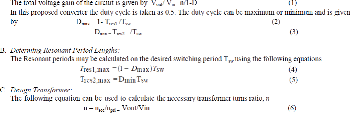 |
SIMULATION RESULTS AND DISCUSSION |
| The comparative analyses of different types of IBR Converter are simulated using MATLAB/SIMULINK Model
which is discussed here. Table 1 shows the different types of IBR Converters and its corresponding input voltage
and output voltage. On this comparative table it clearly shows that the Integrated Boost LCC Resonant Converter
does the maximum step up voltage of 121 V yielding high Efficiency. |
| The Simulink model of the Integrated Boost LCC Resonant Converter as shown in Fig.7 which gives the maximum
output voltage for 12V dc input from solar panel, giving maximum Efficiency. The solar PV
Equivalent Circuit as shown in the Fig.8 is used in the simulation .The output step up voltage of 121V dc is
obtained as shown in Fig.9. |
| The comparison graph showing the rise in the output voltage and output Efficiency for different IBR converter
configurations are shown in Fig.10 and 11.For the Integrated Boost LCC Resonant converter the maximum dc output
voltage was obtained. |
CONCLUSION |
| This paper does a comparative study of different types of IBR Converters for which the best performance was obtained
for the Integrated Boost LCC Resonant Converter, giving high step up output voltage and high Efficiency for Resistive
loads. The best performance IB LCC Resonant converter Simulink model and results are shown in the paper. |
| |
Tables at a glance |
 |
| Table 1 |
|
| |
Figures at a glance |
 |
 |
 |
 |
 |
| Figure 1 |
Figure 2 |
Figure 3 |
Figure 4 |
Figure 5 |
| |
 |
 |
 |
 |
 |
| Figure 6 |
Figure 7 |
Figure 8 |
Figure 9 |
Figure 10 |
| |
 |
| Figure 11 |
|
| |
References |
- C.-E. Kim, G.-W. Moon, and S.-K. Han, “Voltage doubler rectified boost integrated half bridge (VDRBHB) converter for digital car audioamplifiers,” IEEE Trans. Power Electron., vol. 22, no. 6, pp. 2321–2330, Nov. 2007.
- C. Yoon and S. Choi, “Multi-phase dc-dc converters using a boost half bridge cell for high voltage and high power applications,” in Proc. IEEE6th Int. Power Electron. Motion Control Conf., pp. 780–786, May 2009,
- X .Wang, F. Tian, and I. Batarseh, “High efficiency parallel post regulator for wide range input dc-dc converter,” IEEE Trans. Power Electron.,vol. 23, no. 2, pp. 852–858, Mar. 2008.
- C. Lippincott and R. M. Nelms, “A capacitor-charging power sup- ply using a series-resonant topology, constant on-time/variable frequencycontrol, and zero-current switching,” IEEE Trans. Ind. Electron., vol. 38, no. 6, pp. 438–447, Dec. 1991.
- R. Beiranvand, B. Rashidian, M. R. Zolghadri, and S. M. H. Alavi, “Op- timizing the normalized dead-time and maximum switching frequency ofa wide-adjustable-range LLC resonant converter,” IEEE Trans. Power Electron., vol. 26, no. 2, pp. 462–472, Feb. 2011.
- M. Youssef, J. A. Abu Qahouq, and M. Orabi,” Analysis and Design of LCC Resonant Inverter for the Tranportation Systems Applications,”2010 IEEE Applied Power Electronics Conference, Feb. 2010.
- Zhe Li, Chun-Yoon Park, Jung-Min Kwon And Bong-Hwan Kwon,” High-Power-Factor Single-Stage LCC Resonant Inverter For Liquid CrystalDisplay Backlight” IEEE Transactions On Industrial Electronics, Vol. 58, No. 3, March 2011.
- A. Bucher, T. Duerbaum, D. Kuebrich, and S. Hoehne, “Multi -resonant LCC converter - comparison of different methods for the steady-stateanalysis,” Power Electronics Specialists Conference, 2008, pp.1891-1897.
- F. Max Savio, R. Hemantha Kumar and M. Sasikumar , “Power Optimisation and Performance Evolution of High Step-Up Solar PV System ForDc Drives”, International Journal of Advanced Research in Electrical, Electronics and Instrumentation Engineering (IJAREEIE),Vol. 2, Issue 10,October 2013.
- G.Arthiraja, M.AmmalDhanalakshmi, B.Arunkumaran and M. Sasikumar, “Solar PV Based Zeta Converter with Capacitor Multiplier andCoupled Inductor for DC drive Applications ”, International Journal of Engineering and Technical Research (IJETR),Vol. 1, Issue 10, Dec 2013.
- D. C. Martins and R. Demonti, “Photovoltaic energy processing for utility connected system,” in Proc. Ind. Electron. Soc., 2001, vol.no 2, pp.1292–1296..
- Ben York,Wensong Yu and Jin-sheng “An Integrated Boost Resonant Converter for Photovoltaic Applications” IEEE Trans. Power Electron.,vol. 28, no. 3,March 2013.
- Ben York,Wensong Yu and Jin-sheng “Hybrid Frequency Modulation For PWM Integrated Boost Resonant Converters” IEEE Trans. PowerElectron., vol. 28, no. 2,Feb 2013.
- Global Market Outlook for Photovoltaics Until 2014, Eur. PhotovoltaicInd. Assoc. (EPIA), Brussels, Belgium, May 2010.
|