INTRODUCTION
|
| In digital signal processing (DSP) discrete fourier transform (DFT) is a very important technique. For telecommunication, particularly for orthogonal division multiplexing (OFDM)[2] systems fast fourier transform is a critical block. Time complexity (O(N2)) and computational difficulty of DFT increase the FFT. FFT is an efficient method to reduce the time complexity to O(N log2 N) which was proposed by Cooley and Turkey[5], Here N denotes FFT size. |
| Implementation of hardware in various papers[6]-[10] is mainly classified into memory based and pipeline architecture style. Mainly memory based and pipeline architecture is adopted to design FFT processor . Design method composed of a main single processing element (PE) and several memory units. The hardware cost and power consumption of this kind of architecture style is lower. But its disadvantage is long latency, long throughput and it cannot be parallelized. Pipeline architecture can get rid off the disadvantage of the above architecture. |
| In pipeline architecture each stage of FFT using separate arithmetic unit. This approach increase the throughput by a factor of log2N when different units are pipelined. This architecture is also known as cascade FFT architecture and will be used in our proposed design. |
| Pipeline FFT processors have two popular design types. One uses asingle-path delay feedback (SDF) pipeline architecture[6]-[7], and the other uses a multiple-path delay commutator (MDC) pipeline architecture.The single-path delay feedback (SDF) pipeline FFT is good in its requiring less memory space (about N-1 delay elements) and its multiplication computation utilization being less than 50%, as well as its control unit being easy to design. Such implementations are advantageous to low-power design, especially for applications in portable DSP devices. Because of these reasons SDF pipeline architecture is adopted in our design. |
| FFT computation need to multiply input signals with different twiddle factors, which result in more hardware cost because large size ROM is required and it also increase the area. Designing a FFT processor without ROM we can increase the performance and also can reduce the area. Commonly using word length complex multipliers increase the cost so we are using complex multiplier realized with shift and add operation. The architecture design also use of the symmetric property of twiddle factor[1][3]. |
| The rest of this paper is organized as follows. Abrief review of the fast Fourier transform is described in Section II. In Section III presents our proposed FFT architecture. In section IV simulation and result. In section V concluding remarks has given. |
FFT ALGORITHM
|
| The DFTof an N-pointdiscrete-time signal is defined by: |
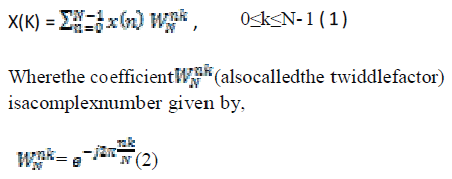 |
| Straight implementation of this algorithm is impractical because large number of multipliers is required for its implementation. So FFT algorithm is required for its efficient implementation and to reduce the hardware cost.Generally, FFT analyses an input signal sequence by using a decimation-in-frequency (DIF) or decimationin- time (DIT) decomposition to construct an efficiently computational signal-flow graph (SFG). |
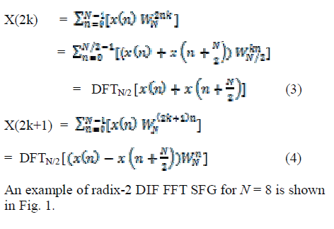
| Decimation in Frequency algorithm Thisalgorithm decomposesevenandodd-indexedfrequencysamples as shown mathematically in equation sets (3) & (4). |
 |
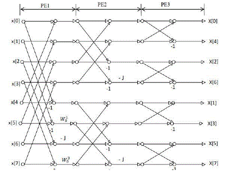
| From figure we can analyse that some complex multiplication can be simplified to reduce the chip area and to avoid ROM. Input signal multiplied by Ws1 in fig can be expressed as: |
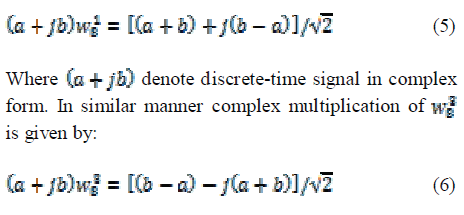 |
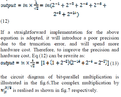
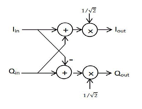
| Both these equations are required for hardware implementation. Multiplication by can be obtained easily by 1/√2 using the bit-parallel multiplier explained in the later section. |
PROPOSED ARCHITECTURE
|
| By considering symmetry of twiddle factors we can reduce the complexity of complex multiplication. Complex multiplication in an FFT must be one of the type given below: |
 |
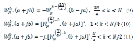 |
| Twiddle factors are generating using cosine and sine functions. Therefore using all the values of sine and cosine function coming between 0-π/4 the complex multiplication with twiddle factors can be done. |
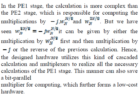
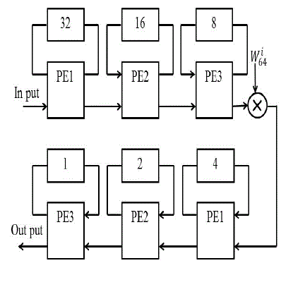
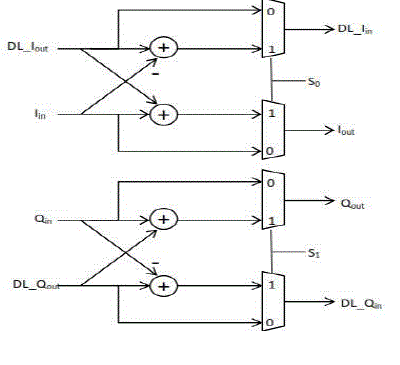
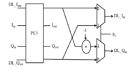
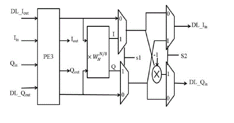
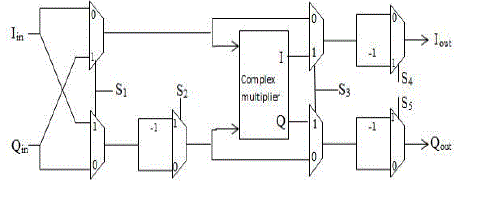
| The proposed architecture is composed of three different types of processing elements (PEs), a complex constant multiplier,delay-line (DL) buffers (as shown by a rectangle with a number inside).The proposed architecture uses single path delay feedback. A reconfigurable complex constant multiplier is used to eliminate the twiddle factor ROM. Thus the new multiplication structure becomes the important component in reducing the area and hardware cost. The proposed architecture is shown in Fig. 2 PE3 stage is used to implement a simple radix-2 butterfly structure only, and serves as the submodules of the PE2 and PE1 stages.In the figure, Iinand Ioutare the real parts of the input and output data, respectively. Qin and Qoutdenote the image parts of the input and output data, respectively. Similarly, DL_Iinand DL_Ioutstand for the real parts of input and output of the DL buffers,andDL_Qinand DL_Qoutare for the image parts, respectively.The working of processing element 3 (PE3) is as follows and illustrated in Fig.3. When So =0, DL_Iin = Iin ,Iout=DL_Iout ,When So=1 , DL_Iin = DL_Iout + (Iin), Iout=Iin+(-DL_Iout).In PE2 stage,we need toperform the multiplication by -1. In PE2 stage, it is required to compute the multiplication by –j or 1. Note that the multiplication by-1 in Fig. 4 is practically to take the 2’s complement of its input value. |
 |
 |
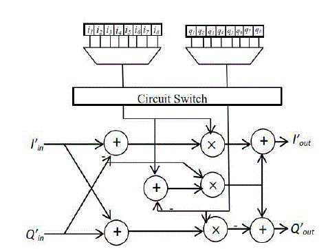
| Multiplication by W is done by a reconfigurable complex constant multiplier. Structure of this complex multiplier also adopts a cascaded scheme to achieve lowcost hardware. Structure is as illustrated in the figure. Circuit in fig.8 is responsible for the multiplication of W in the proposed architecture that is shown in the fig. 2 |
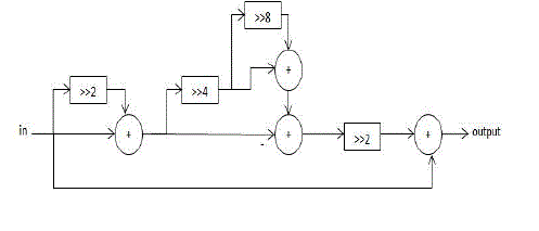
| The multiplier in fig.9 is responsible for the twiddle factor complex multiplication in the reconfigurable complex multiplier shown in fig.8. The coefficient values - and - are listed in table I. The twiddle factors in our proposed design is generating using the values in the table. |
SIMULATION RESULTS
|
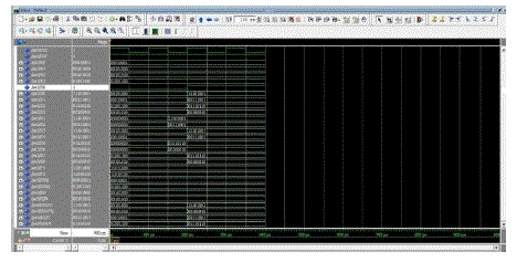
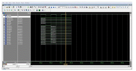
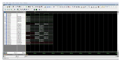
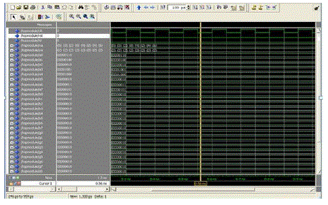
| Simulation of 64-point FFT was described in VHDL and Simulation was done in modelsim and the code was functionally verified to be correct. |
| From the synthesised power report the following result is obtained. The total dynamic power only 2.1875mW and cell leakage power only 43.6134uW. |
CONCLUSION
|
| This approach using without ROM and low-power pipeline FFT for OFDM applications have been described in this paper. Considering the symmetric property of twiddle factors in FFT, we have designed a reconfigurable complex constant multiplier such that the size of twiddle factor ROM is significantly shrunk, especially no ROM is needed in our work. By using proposed structure there should be significant reduction in area and hence power. So the proposed architecture can be used in portable DSP devises. |
Tables at a glance
|
 |
| Table 1 |
|
Figures at a glance
|
 |
 |
 |
 |
 |
| Figure 1 |
Figure 2 |
Figure 3 |
Figure 4 |
Figure 5 |
 |
 |
 |
 |
 |
| Figure 6 |
Figure 7 |
Figure 8 |
Figure 9 |
Figure 10 |
 |
 |
 |
| Figure 11 |
Figure 12 |
Figure 13 |
|
References
|
- Ahmad Salehi, RasoulAmirfattahi, and Keshab K.Parhi(2013)“Pipelined Architectures for Real-Valued FFT andHermitian Symmetric IFFT With Real Datapaths” IEEE transactions on circuits and systems.
- IEEE 802.16, IEEE Standard for Air Interface for Fixed Broadband Wireless Aceess Systems, the Institute of Electrical and Electronics Engineers, Inc., June 2004.
- 3GPP LTE, “Evolved Universal Terrestrial Radio Access (EUTRA); Physical Channels and Modulation” 3GPP TS 36.211 v8.5.0,2008- 12.
- ETSI, “Digital Video Broadcasting (DVB); Framing Structure, Channel Coding and Modulation for Digital Terrestrial Television,” ETSI EN 300744 v1.4.1, 2001.
- J. W. Cooley and J. W. Tukey, “An algorithm for the machine calculation of complex Fourier series,” Math. Comput., vol. 19, pp.297301,Apr.1965.
- S. He and M. Torkelson, “Designing Pipeline FFT Processor for OFDM (de)Modulation,” in Proc. URSI Int. Symp. Signals, Systems, andElectronics, vol. 29, Oct.1998, pp. 257-262.
- H.L. Groginsky and G.A. Works, “A pipeline fast Fourier transform,”IEEE Transactions on Computers, vol. C-19, no. 11, pp.1015-1019, Nov. 1970.
- KoushikMaharatna, Eckhard Grass, and Ulrich Jagdhold, “A 64-Point fourier transform chip for high-speed wireless LAN application using OFDM,” IEEE Journal of Solid-State Circuits, vol. 39, no. 3, pp.484493,Mar.2004.
- Y.T. Lin, P.Y. Tsai and T.D. Chiueh, “Low-power variable-length fast Fourier transform processor,” IEE Proc. Comput.Digit.Tech., vol.152, no. 4, pp. 499-506, July 2005.
- Sungwook Yu and Earl E. Swartzlander, Jr.(2010) “A New pipelined implementation of the Fast Fourier Transform” IEEE transactions on circuits and systems.
|