Keywords
|
| DSP, FFT, FPGA, Fixed_Pkg, Radix-2 algorithm, STD_LOGIC_1164, Synthesis, VHDL, Virtex-5. |
INTRODUCTION
|
| This paper proposes the issues and solutions of synthesis problems of DSP designs to FPGA [6]. DSP algorithms which are designed on VHDL do not guarantee that they are synthesizable [8] to FPGA. It may be possible that these HDL designs do compile and simulate properly on HDL simulators and compilers but still it is not sure that they are completely synthesizable to FPGA [5]. There are several issues which restricts these codes from synthesizing [7]. The FPGA vendors provide their software tools for synthesizing the HDL codes. For synthesizing the HDL design, the libraries and packages used must be supported by these tools [8]. Data type used for HDL designing of DSP algorithm is also an important factor for design synthesis [3]. In this paper, radix-2 based 32-point Fast Fourier Transform algorithm [4] is synthesized to Virtex- 5 FPGA. VHDL design of FFT used for synthesis is developed by following two different ways: |
| 1) Using IEEE fixed point package, ‘fixed_pkg’[2]. |
| 2) Using IEEE package, ‘STD_LOGIC_1164’ [5]. |
| Data types of DSP algorithm is mostly of ‘signed real’ type [3]. VHDL provides various fixed point and floating point data types for representing real type data [1]. Since floating point data type is not efficient for synthesizing to FPGA so fixed point data type is used. For implementing DSP algorithm using only IEEE package, ‘STD_LOGIC_1164’, a method is developed for representing real data type by array of bits. All real arithmetic such as multiplication, addition and subtraction are implemented by specialized algorithms. These algorithms manipulate the bit_vector to implement the real arithmetic. |
RADIX-2 ALGORITHM
|
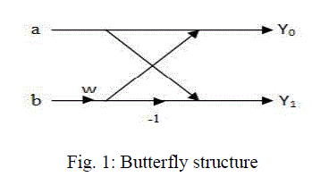
| It is one of the simplest Fast Fourier Transform algorithm in which a Butterfly structure is replicated to get higher order FFT. |
| In replicated butterfly structure we change the values of weighted coefficients ‘w’ as per the position of Butterfly. Radix-2 algorithm may be implemented by either decimation in time or decimation in frequency. In decimation in time algorithm we shuffle the order of input while in decimation in frequency algorithm we shuffle the output. Here decimation in time algorithm is used for implementing 32-Point FFT. |
SIMULATION OF FFT DESIGN USING IEEE FIXED POINT PACKAGE, ‘FIXED_PKG’
|
| IEEE accepted fixed point Package; ‘fixed_pkg’ in VHDL-2008 [1]. This package has powerful operators and functions that specially suits for designing DSP algorithms. 32-Point FFT, radix-2 algorithm is first designed on VHDL using this package then HDL design is comiled and simulated on ModelSim PE Student Edition 10.2a. |
| A. SIMULATION OF BUTTERFLY STRUCTUREq |
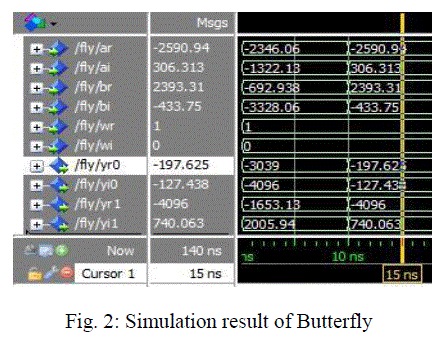
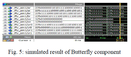
| Here (ar, ai) and (br, bi) are two fixed point real inputs and (yr0 , yi0) and (yr1, yi1) are outputs of Butterfly structure. (wr, wi) is the weighted coefficient of Butterfly structure. Simulation result of Butterfly component is shown in the following figure. |
| B. SIMULATION OF 32-POINT FFT |
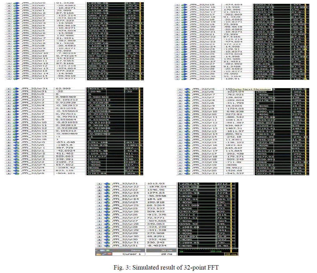
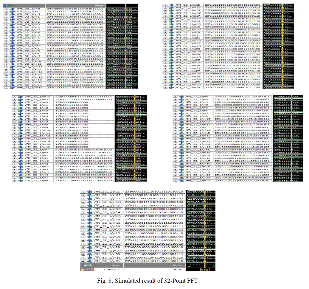
| In this 32- Point FFT design, above simulated Butterfly is used as component. Butterfly component is used in five stages and in each stage sixteen instances of Butterfly are used. Here xr and xi are real and imaginary parts of input x. Similarly yr, yi and wr, wi are real and imaginary parts of y and w respectively. There are 32 complex inputs, 32 complex outputs and 17 different weighted coefficients. Simulation result of 32-Point FFT is shown in the following figure. |
| C. ISSUES ON SYNTHESIZING THIS DESIGN |
| Fixed point package, fixed_pkg is brought to VHDL-2008 by IEEE. It is said that the designs using this package will be synthesizable. All the data structures used in this package are fixed point. |
| This package contains powerful operators and functions which makes it very efficient in designing DSP algorithm. But, still this package is not absolute synthesizable because it is not fully supported by synthesizer tools. |
IMPLEMENTATION OF FFT USING IEEE PACKAGE, ‘STD_LOGIC_1164’ ALONE
|
| For implementing the DSP algorithms using IEEE package, ‘STD_LOGIC_1164’ alone, a data type is required which may implement both the real and complex numbers. Its real data type is of floating point, so it will not be synthesizable. So a method is developed which represent the real and complex numbers by ’bit_vector’. |
| A. REPRESENTATION OF REAL AND COMPLEX NUMBERS BY ‘BIT_VECTOR’ |
| ‘A’ is an array of bits of length ‘L’ in which M bits represents fraction part and N bits represents whole part. A=b(N-1)…..b2b1b0 b1…..b(M-1)bM The numbers N and M are chosen depending on the precision and range of real number. Here important point is that the software and FPGA will treat this array of bits ‘A’ as simply a bit vector of length ‘M+N’. |
| B. ALGORITHMS FOR ARITHMETIC OPERATION ON THIS DATA STRUCTURE |
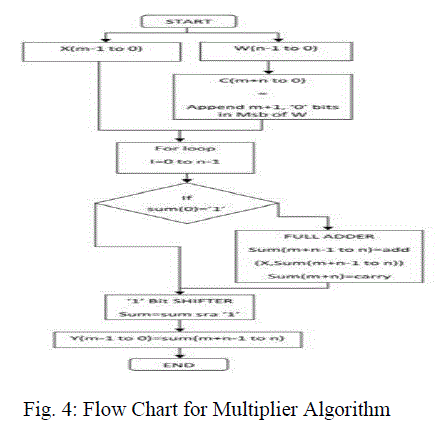
| Specialized algorithms are developed which will operate on above defined data structure and manipulate the array of bits in such a way that they will fulfill the functions of complex and real numbers. For the 32-Point FFT calculation, addition, subtraction and multiplication algorithms are used. Multiplier algorithm is explained in following context. |
| C. ALGORITHM FOR MULTIPLIER |
| This multiplier is designed for multiplication operation in FFT design. It takes two bit vectors as input and gives a bit vector as output with its length equal to multiplicand. |
| D. SYNTHESIS AND SIMULATION OF FFT USING IEEE PACKAGE, ‘STD_LOGIC_1164’ |
| These results are compiled and simulated on Modelsim PE Student Edition 10.2a and synthesized on Xilinx ISE 10.1 design suite. For design simulation ‘Xilinx Virtex-5’ FPGA is used. |
1. SIMULATION OF BUTTERFLY STRUCTURE
|
| Simulated result is shown in the following figure. As it was shown in figure-1, it has two complex inputs, two complex outputs and one complex weighted coefficient. Each input and output is of 23 bits length and coefficient is of 12 bits length. Least significant 10 bits are fraction bits. |
2. SYNTHESIS RESULTS OF BUTTERFLY STRUCTURE
|
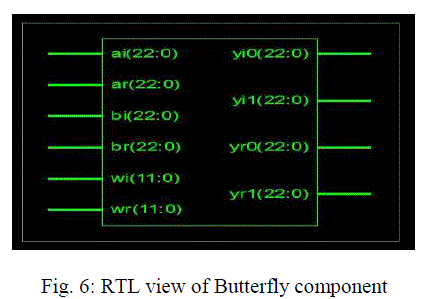
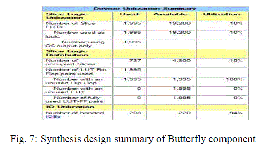
| The HDL design of Butterfly is synthesized with Xilinx ISE 10.1 design suite. RTL view of Butterfly structure is shown in the following figure. This RTL structure is automatically generated after synthesizing the design with Xilinx design suite. The next is synthesis design summary of Butterfly on Virtex-5 FPGA. |
3. TIMING SUMMARY
|
| Maximum combinational path delay of designed FFT-32 on FPGA is 95.814ns. |
4. SIMULATION OF 32-POINT FFT
|
| In the 32-Point FFT design, above described Butterfly design is used as component. Total 80 instances of Butterfly are used in this design. |
5. SYNTHESIS OF 32-POINT FFT
|
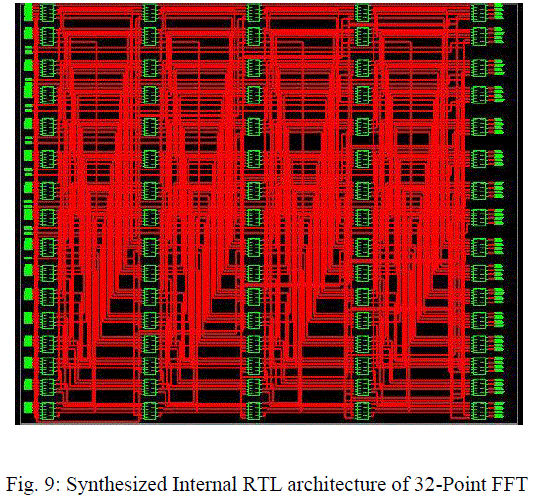
| The proposed design of 32-FFT block is synthesized using the Xilinx ISE 10.1 design suite. Thus the RTL block obtained after synthesizing the design is shown below. |
| From the above synthesized Internal RTL architecture it clear that whole architecture is divided in five stages and each stage comprises sixteen instances of Butterfly, thus total eighty instances of Butterfly are visible in above shown RTL architecture. |
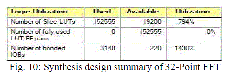
| The next is synthesis design summary of 32-Point FFT on Virtex-5 FPGA, it shows the features of the Virtex-5 FPGA used by Xilinx design suite for proposed work. Maximum combinational path delay: 466.732ns. |
COMPARISON OF RESULT WITH MATLAB 7.11.0.584
|
| Simulated results of synthesizable design of 32-Point FFT using ‘STD_logic_1164’ package are compared with Matlab and the percentage error is calculated for each output. The comparison table is shown below. |
CONCLUSION
|
| The HDL design of 32-Point FFT is implemented with IEEE fixed point package, ‘fixed_pkg’. This design works properly on Modelsim but is non-synthesizable. A new data structure is devised which is actually a bit vector that fulfills all the complex and real data structure needs. This data structure is completely defined by IEEE package,’STD_logic_1164. For implementing DSP algorithms using this data structure some specialized arithmetic algorithms are designed. 32-Point FFT is again implemented with this data structure and this design is absolutely synthesizable. Simulated results of synthesizable 32-Point FFT design are compared with Matlab results, and we get average error of 0.1%. This shows that this method of designing and implementing DSP algorithms is very efficient and completely synthesizable. |
Tables at a glance
|
 |
 |
 |
 |
| Table 1 |
Table 2 |
Table 3 |
Table 4 |
|
| |
Figures at a glance
|
 |
 |
 |
 |
 |
| Figure 1 |
Figure 2 |
Figure 3 |
Figure 4 |
Figure 5 |
 |
 |
 |
 |
 |
| Figure 6 |
Figure 7 |
Figure 8 |
Figure 9 |
Figure 10 |
|
| |
References
|
- 1076-2008- IEEE Standard VHDL Language Reference Manual, DOI: 10.1109/IEEESTD.2009.4772740, 2009.
- David Bishop, fixed Point Package User’s Guide. URL: www.vhdl.org/fphdl/Fixed_ug.pdf.
- Uwe Meyer-Base, Digital Signal Processing With Field Programmable Gate Arrays 3E, 2007
- John G. Proakis, Digital Signal Processing: Principles, algorithms, And Applications, 4E, 2007.
- Charles H. Roth, Digital Systems Design using VHDL, 1998.
- Douglas J. Smith: A practical Guide For Designing, Synthesizing And Simulating Asics And FPGAs Using VHDL Or Verilog, 1996.
- Synthesis Forum of Xilinx, UTL: http://forums.xilinx.com/t5/Synthesis/compilation-of-ieee-proposed-library- fails-ISE-13-2/td-p/200101.
- Software Manual of Xilinx ISE Design suite.
|