ISSN ONLINE(2278-8875) PRINT (2320-3765)
ISSN ONLINE(2278-8875) PRINT (2320-3765)
| M.Jasmin Assistant Professor, Department of ECE, Bharath University Chennai – 600073, India |
| Related article at Pubmed, Scholar Google |
Visit for more related articles at International Journal of Advanced Research in Electrical, Electronics and Instrumentation Engineering
Power consumption of system level on chip communications is becoming more significant in the overall system on chip power as technology scales down. High bandwidth is desired to enhance parallelism for better performance, and the power efficiency on this bandwidth is critical to the overall SoC power consumption. Current bus architectures such as AMBA, Core connect, and Avalon are convenient for designers but not efficient on power. This paper proposes a physical synthesis scheme for on chip buses and bus matrices to minimize the power consumption, without changing the interface or arbitration protocols. By using a bus gating technique, data transactions can take shortest paths on chip, reducing the power consumption of bus wires to minimal. Routing resource and bandwidth capacity are also optimized by the construction of a shortest-path Steiner graph, wire sharing among multiple data transactions, and wire reduction heuristics on the Steiner graph. In this paper, we optimize on-chip bus communications on the tradeoffs between minimal power, maximal bandwidth, and minimal total wire length. Based on AMBA protocols, we modify the bus structure using a “bus gating” technique, and apply optimizations which are biased toward minimal power, but also favor bandwidth and routing resource.
INTRODUCTION |
| Bus vs NoC Bus and network-on-chip (NoC) are the two types of pop- ular on-chip communication architectures. Bus has been widely used for its speed and simplicity, but lacks the communication bandwidth to support parallelism. Bus matrix extends its bandwidth, but not in an e±cient way on power or wires compared to NoC, which is therefore regarded as a better choice for many applications because of its bandwidth capacity, regularity and scalability. However, NoC has relatively large delay, which is a critical disadvantage to system performance, because communications in NoC must take a series of hops on routers in the network. Even with sophisticated routers taking only one clock cycle each hop, the total delay over a long path is still significant. The accumulation of delay on hops is inevitable due to the independency of routers, and it scales up with the number of routers and system complexity. Therefore, we believe bus based communication provides better perfor- mance in delaysensitive systems, because bus delay can be minimized through centralized control and arbitration. On the other hand, the weaknesses such as low bandwidth and wire e±ciency, are not intrinsic in bus. In this paper, we address these issues on bus matrix to make it capable and efficient on-chip communication architecture. Electronic system design is being revolutionized by widespread adoption of the System-on-Chip (SoC) paradigm. The benefits of using such an approach are numerous, including improvements in system performance, cost, size, power dissipation, and design turn-aroundtime. In order to exploit these potential advantages to the fullest, a complete design methodology must adequately address two dimensions of system design. Firstly, it is essential to efficiently and optimally map an application’s computation requirements to a set of high-performance system components, like CPUs, DSPs, application specific cores, memories etc. Secondly, it is equally important to empower a designer with techniques and tools to map the system’s communication requirements onto a well optimized communication architecture that is well suited to the specific application at hand. The focus of this paper lies on the second of these two aspects of system design. Increasing levels of integration are leading to a growing volume and diversity of data and control traffic exchanged among SoC components. As a result, a poorly designed on-chip communication architecture could become a severe impediment to optimal system performance and power consumption. In order to support highperformance components, the on-chip communication architecture must efficiently transport the large volume of heterogeneous communication traffic they generate. Hence techniques to efficiently and optimally map the system’s communication requirements to a target communication architecture need to be included as an integral part of any system design flow |
PROBLEM FORMULATIONS |
| We require the bus synthesis algorithm to generate a bus matrix based on a given communication constraint graph and a placement of master and slave devices. In this way, on-chip bus matrices can be flexibly reconfigured for different system designs and communication patterns. The optimization is on power and wires under the bandwidth requirement given by the graph. Here with AMBA protocols, we can use definition 1 to model the communication graph of bus matrices. |
| Definition 1: A communication graph GC = (Vs, Vt, A) is directed bipartite graph, where Vs is the set of source vertices, Vt is the set of terminal vertices, and A is the set of arcs from Vs to Vt . |
| We denote the set of master devices by Vs, the set of slave devices by Vt.An arc (vi,vj) in GC means master device i needs to access slave device j. Also given are the fixed on-chip locations of these devices. |
| Definition 2: A placement on a communication graph GC is a physical location function P : Vs _Vt _→ R2. |
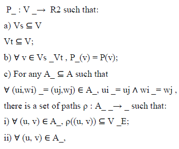
| Definition 3: For communication graph GC = (Vs, Vt,A) and placement function P : Vs _Vt _→ R2, a bus matrix graph is a weighted graph _ = (V, E, ω) with placement |
 |
 |
 |
THE IDEAL BUS MATRIX GRAPH |
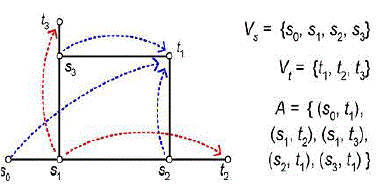 |
| The above fig shows an example of a bus matrix graph connecting fur masters s0, s1, s2, s3 and three slaves t1, t2, t3. Five communication arcs are present: s1 may access t2 and t3, and t1 may be accessed by s0, s2, and s3. The single weight edges in Fig. 5 (by solid segments) are adequate for this requirement. Notice that (s0, t1) is the only arc having more than one shortest paths. And when its connection is on, s2 and s3 cannot access t1 at the same time, i.e., bus lines “s2 ↔ t1” and “s3 ↔ t1” are both open. Depending on s1’s connection, since s1 can take at most one of “s1 ↔ s2” and “s1 ↔ s3,” the connection from s0 can always choose the one other than s1’s and find an open path to t1. This formulation defines an ideal high bandwidth low power on-chip communication solution, but with limited practicality. Because first, minimization on the wire length of _ is computationally expensive due to the exponentially increasing combinations of arc subset A_. And even if we pre-compute the optimal solution, it is still impractical to store the path sets for all the subsets, or to compute the path set _ in real time. Another problem is that, if the communication pattern changes dynamically, when some connections are still on but need to change paths, it may induce extra delay or timing issues. |
HEURISTICS FOR GENERATING SHORTEST-PATH STEINER GRAPHS |
| In our problem of minimal shortest-path Steiner graph, the locations of a set of sources s1, s2, · · · , sm and terminals t1, t2, ..., tn are given, and the objective is to find a rectilinear routing solution containing all the source-to-terminal shortest paths, with total wire length as small as possible. In single source cases, this is a rectilinear Steiner arborescence (shortest-path tree) problem which has been studied. Finding the exact solution of a minimum rectilinear Steiner tree (MRST) is NP-complete [7], and finding |
| a minimum rectilinear Steiner arborescence (MRSA) is believed to be hard [15] although without hardness proof. For practical use, several efficient heuristic algorithms are introduced and compared in [5], among which the 2-IDeA/G algorithm has the best average performance over runtime. In general cases containing multiple sources, the problem has not been studied before. We adopt the the 2- IDeA/G heuristic as basis and add more heuristics to construct the shortest-path Steiner graph. k- IDeA/G heuristic for MRSA The k-IDeA/G (iterated k-deletion for arborescence) algorithm is based on the RSA heuristic (denoted RSA/G). The basic flow of RSA/G is to start with n terminals as n subtrees and iteratively merge a pair of subtree roots v and v_ such that the merging point is as far from the source as possible, so that the wires can be shared as much as possible. It terminates when only one subtree remains. For efficient implementation, the RSA/G first sorts all the nodes on the Hanan grid in decreasing distance to the source s, and visits each node maintaining a peer set P of subtree roots. We denote the rectilinear distance from s to v as Δs(v) or Δ(s, v). Two basic operations are used in RSA/G at: terminal merger opportunity (TMO), when a terminal is added into P as a subtree; and Steiner merger opportunity (SMO), when |X| ≥ 2 and the subtrees in X are merged. |
THE RSA/G ALGORITHM |
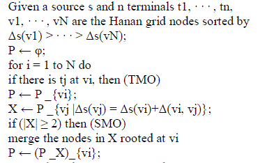 |
| return the arborescence rooted at s;remove up to k nodes from v1, · · · , vN when running the RSA/G algorithm. By removing some nodes, the SMO |
| merges are skipped at those points, which in some cases can result in better overall solution. In each iteration of the k-IDeA algorithm, all the combinations of skipping k or less nodes are tried in the RSA/G and the best set of skipped nodes are marked as permanently deleted. The iterations are then repeated until no further improvement is obtained. |
MULTIPLE MRSA CONSTRUCTION WITH SHARED WIRES |
| With multiple sources s1, · · · , sm, our algorithm needs to construct a Steinter graph G which contains all the MRSAs starting form every source. While each MRSA is minimized by k-IDeA, the m arborescence should share as much wire as possible to minimize total wire length on G. We devise additional heuristics based on k-IDeA to construct multiple MRSAs one by one, explained as follows. First, on each MRSA (rooted at si on ith iteration) construction, the terminals requiring connections can move towards the source si along existing edges of G, so that the wires can be reused and shared. we only need to connect 8 nodes instead of the original 16 terminals to form the MRSA rooted at s2, because all the other terminals can be reached from one of these nodes with shortest path from s2. This set of nodes (denoted T_) can be obtained by checking each terminal tj , which necessitates a shortest-path connection from si. Starting from ti, we move towards si as much as possible along existing wire paths until reaching a vertex v (a terminal or a Steiner node) in G where no vertex closer to si can be reached, then add it to T_. When there are multiple paths in the graph, we pick the final vertex closest to si so the rest part of the path is short and likely to need less wire. |
Nodes requiring connections |
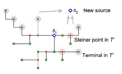 |
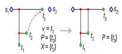
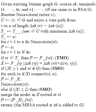
| Second, we construct the MRSA on the set of nodes T_ using existing wires. The TMO condition is then changed to vi ∈ T_. The SMO condition is changed, also for the purpose of wire reusing, from |X| ≥ 2 to |X| ≥ 2 or (|X| = 1 and vi ∈ G). Because when vi is already in the graph, it can share wires with the node in X like the case when |X| ≥ 2 in RSA/G. As figure 6 shows, when X contains only one node {t2}, it should be connected into G when vi comes to t3, and half of the connection length can be saved using the existing horizontal wire. The detailed algorithm is described in table 2, where routine ‘connect (u, v)’ uses existing wires if applicable on shortest connections. |
Connecting a node into the Steiner graph |
 |
REVISED RSA/G’ ALGORITHM |
 |
| The k-IDeA iterations remain unchanged. After the shortest path Steiner graph is constructed by applying k-IDeA on the m sources, there are possibly some redundant edges that can be removed. So the final step is to check each edge (vi, vj) ∈ G, if G still contains all the master-to-slave shortest paths without (vi, vj ), |
| remove edge (vi, vj ). Practical Bus Matrix Synthesis Formulation Given a communication graph GC and its placement, we define another bus matrix graph with fixed paths for the arcsin GC, i.e., each pair of master-slave connection always takes the same path regardless of other connections. |
BUS MATRIX CONTROL DESIGN |
| Apart from path lengths and data wire lengths, the control overhead needs to be considered for a complete optimization. Although the data lines consume the major amount of routing resource because they are usually at least 64 bit (32 bit × 2-way) wide, control overhead is increased compared to traditional bus architectures by adopting Steiner graphs. We need a lot of switches at Steiner nodes to guide the on-chip traffic, and each switch needs a certain number of control signals depending on its node degree and edge weights. |
Control on switches in a bus matrix |
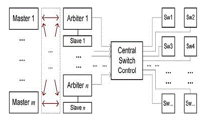 |
| The sketch of bus matrix control scheme |
| Each slave device has an arbiter which handles the requests from masers and decides the connection. The result is sent to the central switch control unit, where all the connection paths are stored. Depending on the set of active paths, the central switch control sends control signals to all the switches on each path, which together instantly create the master-to-slave connection requested by the master device. |
CONCLUSION |
| The weaknesses of original bus matrices, such as low power efficiency and low wire efficiency, are resolved by using a Steiner graph structure. Compared to network-on-chip which has better bandwidth flexibility, bus matrix has much less latency because of its centralized control, consumes less power because of the shortest (or close to shortest) paths with minimal control/packet overhead Efficiency on bus lines is maximized without the need to redesign system components and IP modules Routing resource is also reduced without compromising low power. |
| Therefore, we believe bus matrix architectures will be widely applied for efficient communications in various future systems. |
References |
|