ISSN ONLINE(2278-8875) PRINT (2320-3765)
ISSN ONLINE(2278-8875) PRINT (2320-3765)
M.Bharathi, Golden Kumar
|
| Related article at Pubmed, Scholar Google |
Visit for more related articles at International Journal of Advanced Research in Electrical, Electronics and Instrumentation Engineering
In this project an attempt has been made to adopt an LQR controller design approach for PITCH axis stabilization of 3DOF Helicopter System. The presentation in this report is not limited to only design a controller for the stabilization of PITCH axis model of 3DOF Helicopter but at same time it shows good performance. Some useful basic control systems concept related to Riccaati equation, controllability of the system and PID controller have been also presented to understand the content of the project. The report first develops a transfer function and state space model to represent the PITCH axis dynamics of 3DOF Helicopter system and then LQR controller design steps are explained in brief. The investigated state feedback controller design technique is an optimal design method and it is directly applicable to unstable pitch axis model of 3DOF Helicopter. To show the effectiveness of the investigated method, the report also demonstrates the comparative studies between LQR and PID controllers. The results of the closed loop system performance with LQR controller and PID controller separately are also shown.
1.INTRODUCTION |
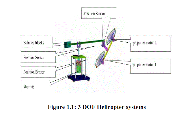
| 3DOF Helicopter System (shown in Fig. 1.1) is composed of the base, leveraged balance, balancing blocks, propellers and some other components. Balance posts to base as its fulcrum, and the pitching. Propeller and the balance blocks were installed at the two ends of a balance bar. The propeller rotational lift, turning a balance bar around the fulcrum so pitching moves, using two propeller speed difference, turning a balance bar along the fulcrum to do rotational movement. Balance the two poles installed encoder, used to measure the rotation axis, pitch axis angle, in the two propeller connecting rod installed an encoder, which is used to measure overturned axis angle. Two propellers using brushless DC motors, provide the impetus for the propeller. By adjusting the balance rod installed in the side of the balance blocks to reduce propeller motor output. All electrical signals to and from the body are transmitted via slip ring thus eliminating the possibility of tangled wires and reducing the amount of friction and loading about the moving axes.Preparation of the experimental guidance on the purpose is to tell users how to design a controller, to control the helicopter in accordance with the desired angle and speed of movement. |
 |
| The theory of optimal control is concerned with operating a dynamic system at minimum cost. The case where the system dynamics are described by a set of linear differential equation and the cost is described by a quadratic functional called LQ problem, one of the main results in the theory is that solution is provided by the LQR, a feedback controller. First, we make a detail analysis and modelingon 3DOF helicopter from its mechanism and features and get its modeling motion equations by the knowledge of physics. From the analysis of the model, the system is with the problem of non-linear and state interference. First, we get the linear state space through linearity of the system, and then we use the theory of LQR to get the optimal state feedback controller from the linear state space. |
1.2 Motivation |
| The motivation for doing this project was primarily an interest in undertaking a challenging project in an interesting area of research. I found the 3DOF Helicopter system as an appropriate area of research of my interest, and using LQR controller design methods for checking its controllability and robustness was my contribution in this research paper. LQR controller is usually used in industry especially in chemical process and aerospace industry. LQR problem is one of the most fundamental and challenging control problems and inthis method; controller is very easy to design and also increases the accuracy of state variable by estimating the state. It takes care of the tedious work done by the control system engineers in optimizing the controllers. However the engineer needs to specify the weighting factor and compare the result with the specified desired goals. This means that the controller synthesis is an iterative process, where the engineer judges to produce optimal controllers through simulation and computation and then adjusts the weighting factor to get a controller more in line with the specified design goals this computing and simulation work for controller synthesis, motivated us to work on this project. |
| 1.3Objectives |
| Design and simulation of LQR controller for pitch axis stabilization of 3 DOF helicopter system (using MATLAB). |
II. MATHEMATICAL MODELLING |
| It is composed of the base, leveraged balance, balancing blocks, propellers and some other components. Balance posts to base as its fulcrum, and the pitching. Propeller and the balance blocks were installed at the two ends of a balance bar. The propeller rotational lift, turning a balance bar around the fulcrum so pitching moves, using two propeller speed difference, turning a balance bar along the fulcrum to do rotational movement. Balance the two poles installed encoder, used to measure the rotation axis, pitch axis angle, in the two propeller connecting rod installed an encoder, which is used to measure overturned axis angle. |
| Two propellers, using brushless DC motors, provide the impetus for the propeller. By adjusting the balance rod installed in the side of the balance blocks to reduce propeller motor output. All electrical signals to and from the body are transmitted via slip ring thus eliminating the possibility of tangled wires and reducing the amount of friction and loading about the moving axes. |
| Three differential equations to describe the dynamics of the system. A simple set of differential equations is developed as follows: |
| 2.1 Pitch axis |
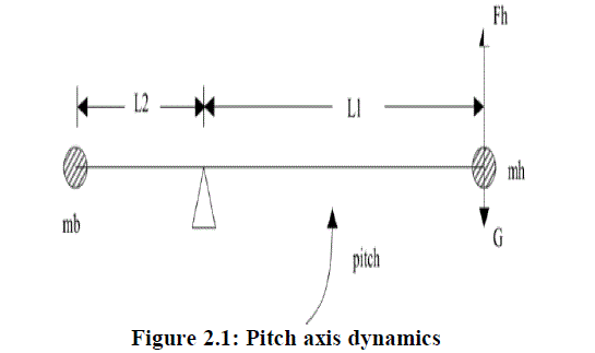
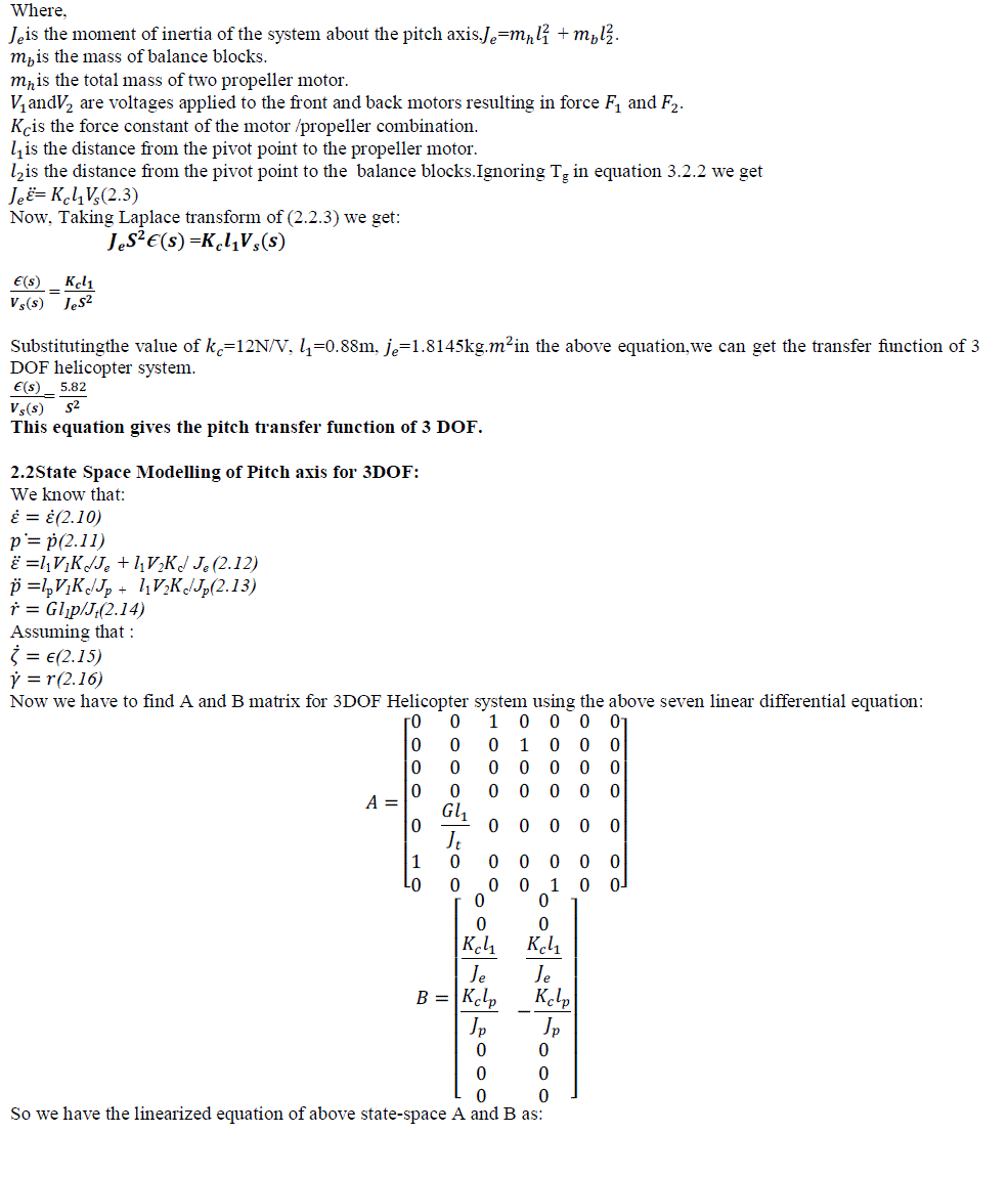
| Consider the diagram in Fig.2.1 Assuming the roll is zero, then the pitching axis torque by two propeller motors lift the F1 and F2. Therefore, the pitch propeller axis total lift FhïüÃÂF1ïüÃâ¹F2.When the lift Fh is greater than the gravityGHelicopter rise. Instead the helicopter dropped. Now,assuming zero roll, the differential equation is: |
 |
 |
 |
 |
III.RESERACH METHODOLOGY |
| 3.1 LQR controller design method |
| The LQR optimal control principle is, by system equations: |
| XÃÅÃâ¡= AX + Bu |
| Determine matrix K that gives the optimal |
| Controlvector:u (t) = -K*x(t) |
| Such that the performance index is minimized: |
| In which Q is positive definite (or semi -positive definite)hermitian or real symmetric matrix R is positive definite hermitian orreal symmetric matrix. |
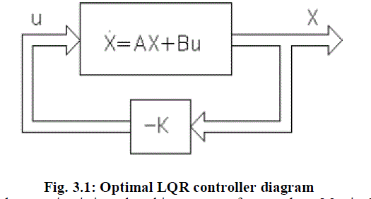 |
| The second term on the right of the equation is introduced in concern of energy loss. Matrix Q and R determine the relative importance of error and energy loss. Here, it is assumed thatthe controlvector u(t) is unbounded. |
| Weighting Matrices selection |
| One way of expressing the performance index mathematically is through an objective function of this form: |
 |
| Here, the Scalars q1...,qn, r....,rm can be looked upon as relative weights between different performance terms in the objective J. The key design problem in LQR is to translate performance specifications in terms of the rise time, overshoot, bandwidth, etc. into relative weights of the above form. There is no straightforward way of doing this and it is usually done through an iterative process either in simulations or on an experimental setup. Once the matrices Q and R are completely specified, the controller gain K is found by solving the Riccati equation. |
 |
| Where according to Bryson’s rule: |
| Q11 is1/ maximum acceptable value of (pitch angle) 2 |
| Q22 is 1/ maximum acceptable value of (roll angle) 2 |
| Q33 is 1/ maximum acceptable value derivative of (pitch angle) 2 |
| Q44 is 1/ maximum acceptable value of derivative of (roll angle) 2 |
| Q55 is 1/ maximum acceptable value of (travel rate) 2 |
| Q66 is 1/ maximum acceptable value of (damping ratio) 2 |
| Q77 is 1/ maximum acceptable value of (ïÿýïÿý) 2 |
| Substituting the above values: |
| Q = |
| 3.2 PID controller design approachpitch axis of 3DOF Helicopter system |
| The PID control scheme is named after its three correcting terms, whose sum constitutes the manipulated variable. The proportional, integral, and derivative terms are summed to calculate the output of the PID controller. |
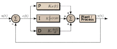 |
| Figure 3.2: PID controller |
| As seen in Fig.2.2 the different terms associated with the controller and its operations are being explained in detail below. The block contains the three different parameters namely Proportional, Integral and derivative. The final form of the PID algorithm is: |
| (3.0) |
| Where, =Proportional Gain, =Integral Gain, |
| =Derivative Gain, e =Error, t =Instantaneous time |
| Proportional term |
| The proportional term produces an output value that is proportional to the current error value. The proportional response can be adjusted by multiplying the error by a constant called the proportional gain constant. A high proportional gain results in a large change in the output for a given change in the error. If the proportional gain is too high, the system can become unstable. |
| Integral Term |
| The contribution from the integral term is proportional to both the magnitude of the error and the duration of the error. The integral in a PID controller is the sum of the instantaneous error over time and gives the accumulated offset that should have been corrected previously. The accumulated error is then multiplied by the integral gain and added to the controller output. The integral term eliminates the residual steady-state error that occurs with a pure proportional controller. |
| Derivative Term |
| The derivative of the process error is calculated by determining the slope of the error over time and multiplying this rate of change by the derivative gain. The magnitude of the contribution of the derivative term to the overall control action is termed the derivative gain. The derivative term slows the rate of change of the controller output. Derivative control is used to reduce the magnitude of the overshoot produced by the integral component and improve the combined controller-process stability. |
| Pitch PID Controller |
| The Pitch axis model is given by equation (2.3): |
 |
IV.RESULTANALYSIS |
| 4.1 Controllability of the system |
| system is said to be controllable at time t, if it is possible by means of an unconstrained control vector to transfer the system from any initial state x(t) to any other state in a finite interval of time. In fact, the conditions ofcontrollability may governthe existence of a completesolution tothe control system design problem. The solution tothis problem may notexist if the systemconsidered is not controllable. Although most physical systems are controllable, corresponding mathematical models may not possess the property of controllability.Then it is necessary to know the conditionsunder whicha systemis controllable. |
| 4.1.1 Complete State Controllability of Continuous-Time Systems: |
| Consider the continuous-time system. |
| xÃÅÃâ¡= AX + Bu (4) |
| Where: |
| x = statevector (n-vector),u = control signal (scalar) , |
| A = n X n matrix, B = n X 1 matrix |
| The system described by Equation (4.0) is said to be state controllable at t = to if it is possible to construct an unconstrained control signal that will transfer an initial state to any final state in a finite time interval to t0≤t≤t1,. If every stateis controllable, then the systemis said to be completely state controllable. |
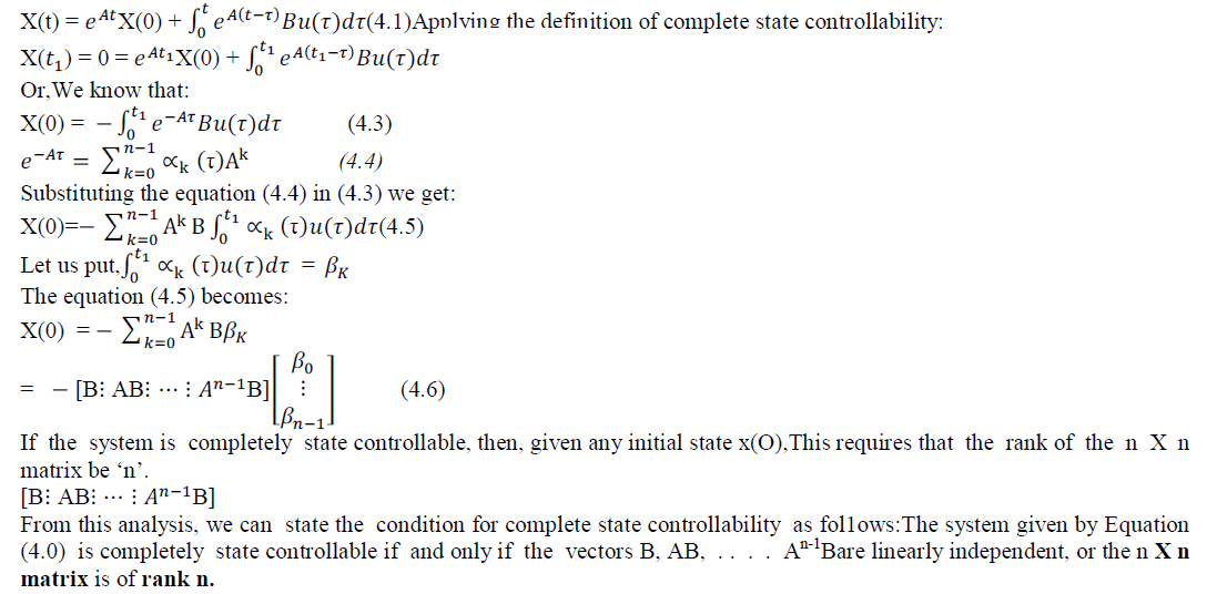
| We now derive the condition for complete state controllability. Without loss of generality, we can assume that the final state is the origin of the state space and that the initial time is zero |
| The solution of equation (4.0) is: |
 |
 |
 |
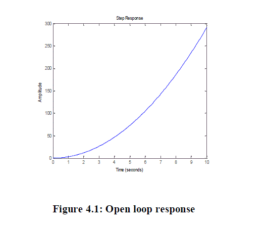 |
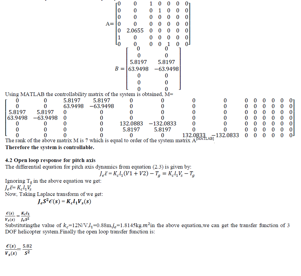
| The Pitch axis model of Helicopter system is unstable as it gives unbounded output for the bounded input signal. It is shown in the figure 4.1 |
| 4.3 State feedback controller of Pitch axis model for Helicopter system: |
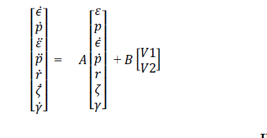
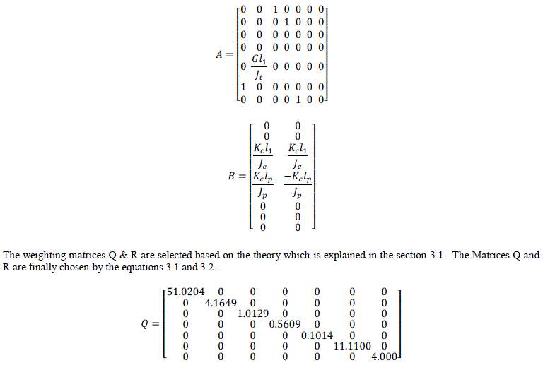
| The plant state space model is already explained in section 2.2.4 and it follows that |
 |
 |
| Here, all the closed loop poles (Eigen values) of the system are either lying in the left half of the s-plane or on the imaginary axis, therefore our designed system is stable. |
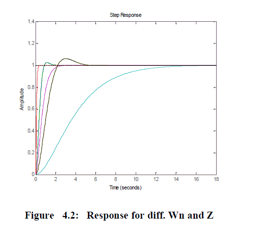
| Natural frequency and damping ratio of the closed loop system is also found using MATLAB code:[Wn,Z,P]=damp(AB* K)and we found that response for the 2nd order system for each value of natural frequency (Wn) and damping factor (Z) are acceptable. It is shown in the following figure. |
 |
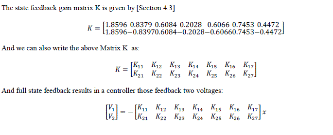
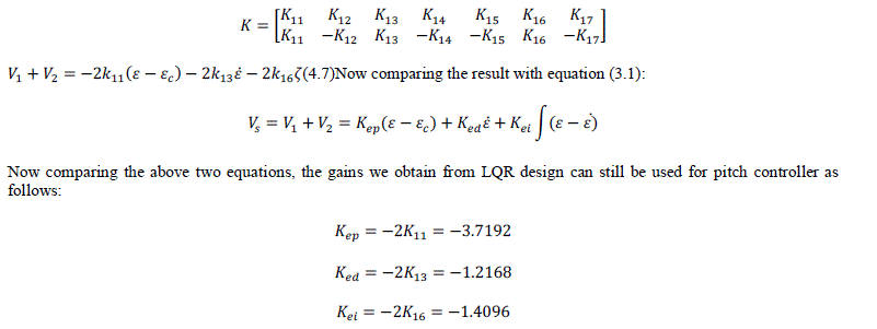
| 4.4 Pitch PID Controller using the values of state feedback gain K |
 |
 |
| 4.4.1 Simulation results |
| Using equation 3.3 the closed loop transfer function of the system is given by: |
 |
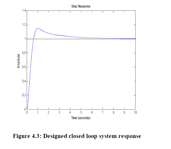
| The response of the above closed loop transfer function is obtained and it is shown in figure 4.3. |
 |
 |
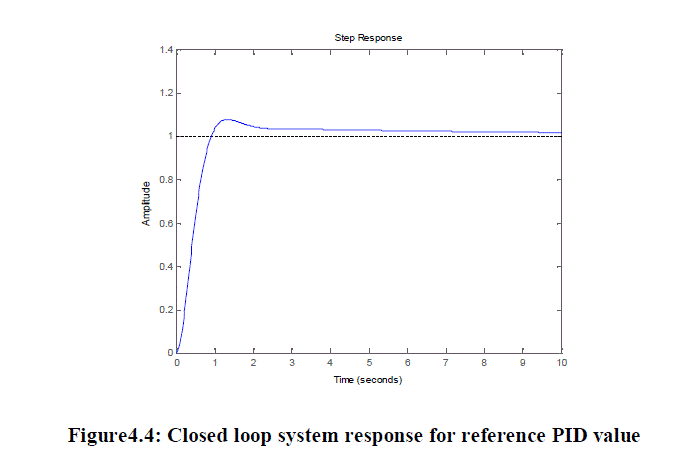
| The response of the above closed loop transfer function is obtained and it is shown in figure 4.4. |
 |
| 4.4.2 Real time system response |
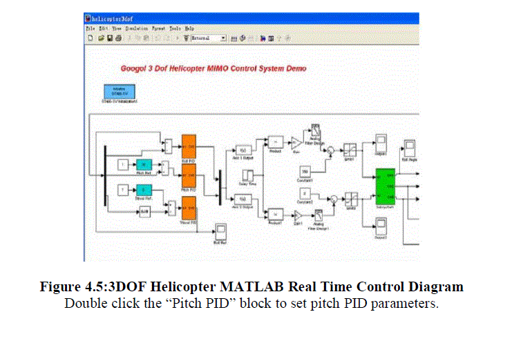
| The real time simulation is done using Helicopter PID control diagram [6] |
 |
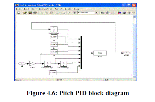 |
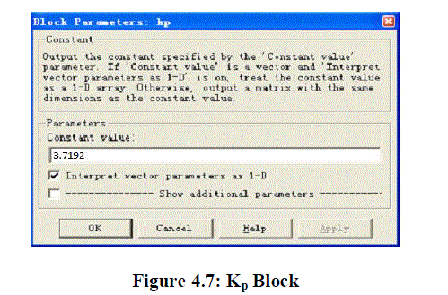
| Double click the “Kp” block to set proportional parameter of pitch PID as the simulation results, and double click “OK” to save parameters. |
 |
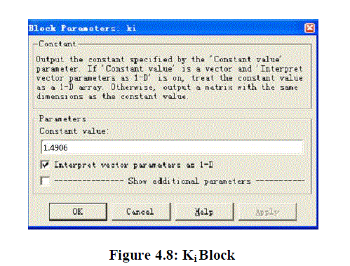
| Double click the “Ki” block to set integral parameter of pitch PID as the simulation results, and double click “OK” to save parameters |
 |
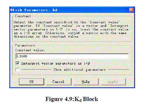
| Double click the “Kd” block to set derivative parameter of pitch PID as the simulation results, and double click “OK” to save parameters. |
 |
| Case 1: System response for 35 degrees (reference) pitch angle |
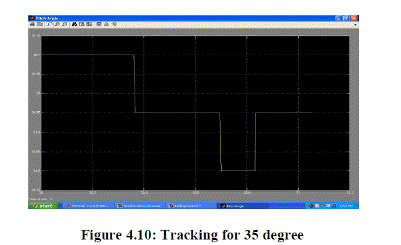 |
| Result: We found that system is stable and tracking the reference input succesfully. |
| Case 2: System response for 45 degrees: |
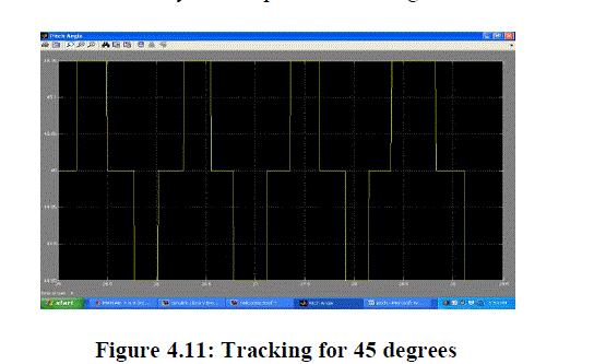 |
| Result: In this case also system is stable and tracking the input signal. |
| Case 3: System response for 55 degrees:- |
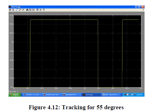 |
| Result: The system is stable and tracking the reference signal. |
| 4.6 Comparative studies between LQR and PID controllers |
| The PID controller parameters Kp, Kdand Ki have been found using LQR state feedback gain matrix K [section 4.3] and then closed loop system performance analysed. The following time domain performance parameters are obtained. |
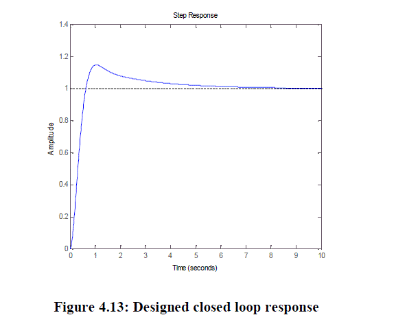 |
| RiseTime: 0.4291s,Settling Time: 4.8948sOvershoot: 14.6289%,Peak: 1.1463,Peak Time: 1.0470s |
| Again we have taken PITCH PID controller values and closed loop system response obtained which is shown in the figure |
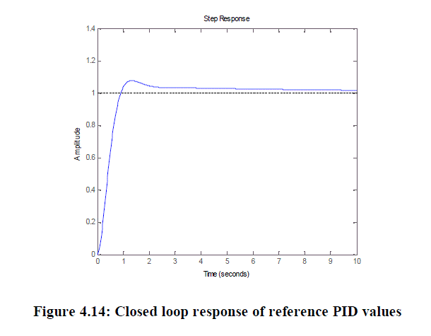 |
| Rise Time:0.6021s,Settling Time:7.9956s,Overshoot: 7.6368%Peak: 1.0764,Peak Time: 1.3321s |
V.CONCLUSION AND FUTURE SCOPE OF WORK |
| 5.1 Conclusion |
| In this project an optimal design approach has been chosen to design a state feedback controller for PITCH axis model of 3DOF Helicopter system. First we developed the Mathematical model of 3DOF Helicopter system and then stability & performance of the modelled system is carried out. |
| The theory of LQR controller design has been investigated and a different approach based on Bryson rule has been also adopted to select the weighting matrices which are used in controller synthesis. |
| The selected project is also demonstrated successfully in real time platform and it is followed by the comparison with existing design. Simulation analysis is also shown in the report. |
| 5.2 Future Work: |
| In this project an LQR controller is synthesized for PITCH axis stabilization for 3 DOF helicopter systems and the same approach can be extended for Travel and Roll axes for the same system. |
References |
|