ISSN ONLINE(2278-8875) PRINT (2320-3765)
ISSN ONLINE(2278-8875) PRINT (2320-3765)
| T.Jayachitra, V.K Pandey and Anshuman Singh, Noida Institute of Engineering and Technology, Greater Noida, UP, India |
| Related article at Pubmed, Scholar Google |
Visit for more related articles at International Journal of Advanced Research in Electrical, Electronics and Instrumentation Engineering
Hybrid couplers are widely used in microwave circuit design. The principle of a hybrid coupler is that the input power is split equally between the coupled and through ports, with a 90 degree phase difference. The fourth (isolated) port is terminated by a 50- ohm load. Hybrid coupler can be directly connected to microstrip antenna to get circular polarization. Microstrip patch antennas being popular because of light weight, low volume, thin profile configuration which can be made conformal. Wireless communication systems applications circular polarization antenna is placing vital role. In this study the hybrid coupler is designed for 2.4GHz with impedance (z0) is 50Ω, dielectric constant εr is 4.6 and thickness of dielectric material is 1.6mm. Simulation is done by ADS software
Index Terms |
| Hybrid Coupler, Microstrip antenna, Polarization, Quadrature hybrid, 3 dB hybrid coupler |
INTRODUCTION |
| In power divider, hybrid is a special case where the signals at the two output ports are equal and differ in phase by 90 degree. They are used in amplifier systems where solid state power is insufficient during individual amplifier limitations, power enhanced by using multiple amplifiers in a hybrid network. By choosing appropriate capacitance the circuit can act as a quadrature amplitude-tunable power splitter [1] and by cascading hybrids in a tree/ a matrix divider/combiner configuration, more power is transmitted, as well as improving the efficiency of the transmission [2]. The types of power divider are as follows. |
The Quadrature Hybrid |
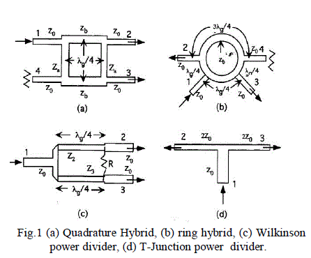
| The quadrature hybrid is shown in Figure 1a. It is a four-port network, the input is at port 1 and the output ports 2 and 3, when port 4 is terminated in a match load. Alternatively, port 4 is the input and port 1match – terminated when the output remains at ports 2 and 3. The operation of the hybrid is not affected when ports 1 and 4 are interchanged with ports 2 and 3 because of a high degree of symmetry [3]. |
| Ports 1 and 4 or vice versa are assigned with the input based on the required logic of circular polarization. Meanwhile, ports 2 and 3 are provided for the output. |
| However, the signal is split into amplitude; ports 2 and 3 are allocated with in phase quadrature. Inconsistency might happen at port 4 due to the patch returns to the absorbing load. Port 2 and 3 are uncoupled, good isolate, and surpassing 20 dB exists between the outputs. Therefore, the axial is not degraded. Four port direct coupled power divider is used for designing a 3-dB quadrature hybrid. The characteristic impedances Za and Zb of a quarter-guide wave length shunt and series arms are obtained in terms of Zb- Z0/√2 and Za-Z0 |
| 3 dB, 90 degree hybrids are recognized as construction hybrids. As a result, sign is applied to any input to divide it into two equal amplitude signals rather than 90 degree. It won’t create any difference since the outputs remains as similar as these devices square measure electrically and mechanically balanced. This relationship ensures a high degree of isolation between the two output ports and therefore the two input ports do not need interaction between them. |
The 180-Degree Ring Hybrid |
| The ring hybrid is a 180-degree hybrid junction, as shown in Figure 1b. The input given at Port 1 is equally divided into amplitude and phase and applied at ports 2 and 3 which are all linked with the patch dualorthogonal feeds. A quadrature phase difference among the two orthogonal excitations can be attained using a quadrature wave length differential line length between the two outputs lined. Due to the 90 degree phase shift between the output arms, at port 1 the reflection from the patch is getting cancelled. Therefore ports 2 and 3 are uncoupled and the outputs are having good isolation. It is usually better than 20dB. The sense of circular polarization rotation can be changed, if port 4 becomes the input and port 1 is match-terminated while keeping everything else the same. The line parameters can be obtained from the general design equations of a hybrid-ring coupler. For a 3-dB split, the characteristic impedance of the ring Zb is found to be Z0 [3]. |
Wilkinson power divider |
| Figure 1c represents that, the input at port 1 consistently characterized according to the amplitude and phase at output ports 2 and 3. According to the ring hybrid, the dual feeds can be recognized by quarter wavelength line among output ports 2 and 3 at the level of 90 degree phase. Therefore, the result placed among any two level output ports at 90 degree phase while it finds any reflection at the patch as odd mode excitation can degenerate in the isolation resistor |
| But, the antenna reliability will be decrease while maintaining good matching [3]. |
 |
3 dB Quadrature Hybrid Coupler |
| A 3 dB, 90° hybrid coupler is a four-port device, that is used either to equally split an input signal with a resultant 90° phase shift between output signals or to combine two signals while maintaining high isolation between them. However, in a practical device the amplitude balance is frequency dependent and departs from the ideal 0dB difference. All 90° Power Dividers/Combiners, also known as quadrature hybrids or simply quad hybrids, are reciprocal four port networks . Figure 2 is a functional block diagram of a 3 dB quad hybrid coupler. The hybrid coupler, or 3 dB directional coupler, in which the two outputs are of equal amplitude, takes many forms. It is beginning when quadrature (90 degree) 3 dB coupler coupling with outputs 90 degrees out of phased. Now any matched 4-port with isolated arms and equal power division is called a hybrid or hybrid coupler. Now a days the characterizing feature is the phase difference of the outputs In an ideal hybrid circuit, the difference should be 0 dB. |
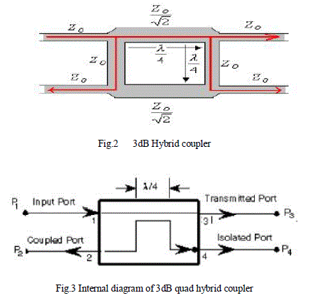 |
| Referring to Figure 3, a signal applied to port 1 splits equally between ports 2 and 3 with one of the outputs exhibiting a relative 90° phase shift. If ports 2 and 3 are properly terminated into matching impedances, nearly all the signal applied to port 1 is transmitted to the loads connected to ports 2 and 3. In this circumstance, port 4 receives negligible power and is termed as isolated. However, if there is an impedance mismatch at port 2, for example, then signal power reflected back from port 2 were divided proportionally between ports 1 and 4 and power is not fed to port 3.In this paper ,design of 3 dB 90 degree hybrid coupler is done. |
II. DESIGN OF HYBRID COUPLER |
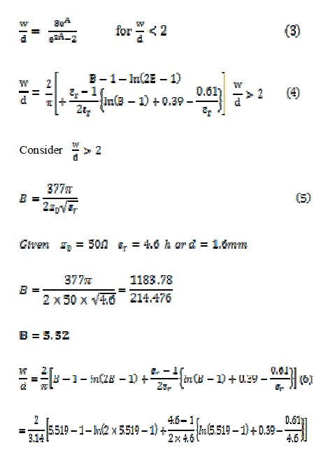
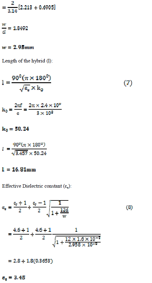
| Thickness of the Substrate is taken as 1.6 mm and dielectric constant 4.6. Operating frequency has chosen as 2.4Ghz. The design of Hybrid coupler is as follows |
 |
 |
III. RESULTS AND DISCUSSION |
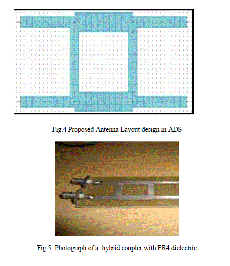
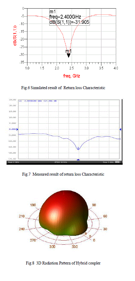
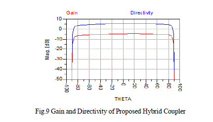
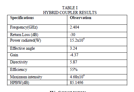
| The simulation of 3 dB hybrid coupler is done on ADS software and we get simulation results of return loss, Gain, 3D E- fields. Figure 5 depicts the resonating frequency of proposed hybrid coupler is 2.4 GHz and the return loss is - 31.905dB. This low value of return loss yields higher efficiency in WLAN applications. Figure 4,5 shows the layout and photograph of a hybrid coupler on FR4 PCB . Figure 6 and 7 shows the return loss characteristic of simulated and fabricated antenna, both are in a good agreement. Figure 8 shows the 3D radiation pattern and Figure 9 shows the gain and directivity of the hybrid coupler. The simulated and measured results satisfy the requirements of wireless communication. |
 |
 |
 |
 |
IV. CONCLUSION |
| In this paper, 3 dB hybrid coupler was choosen. The hybrid coupler is designed to operate at 2.404 GHz frequency. The hybrid coupler is successfully implemented and fabricated. The performance of the simulated and fabricated hybrid coupler agreed well. The 3 dB hybrid coupler can be connected with patch antenna to produce circular polarization. |
References |
|