ISSN ONLINE(2278-8875) PRINT (2320-3765)
ISSN ONLINE(2278-8875) PRINT (2320-3765)
B. Dheeraj Reddy1, Dr. Sarat Kumar Sahoo2
|
| Related article at Pubmed, Scholar Google |
Visit for more related articles at International Journal of Advanced Research in Electrical, Electronics and Instrumentation Engineering
Transformers are designed so as to minimize weight and cost based on three presumptions: the power supply is with a sine wave, the frequency is fixed, and the voltage not to exceed a prescribed maximum limit. Fastidious approach in designing the transformer based on these assumptions is not entailed, then again proper consideration is required if the assumptions are amended. Given this as beginning, an efficient and cost-effective design has to be resolved. In order to reduce the emission of greenhouse gas and replace the limited energy sources like coal or oil, the number of renewable energy sources is constantly growing. All these points led to have a best solution which was the reason for evolution of Solid State Transformer. This paper presents the constructional details of a 100 VA, 100 Hz and 200 VA, 50 Hz transformer and compares the results to claim the best design.
Keywords |
| Solid State Transformer (SST), Power Electronic Devices, SST Topology, Smart Grid. |
I.INTRODUCTION |
| The conventional “behemoth” transformers, highly efficient and reliable, suffer certain demerits: sensitive to harmonics, no power factor improvement, poor performance under dc-offset load unbalances, voltage drop under load, no protection from system disruptions and overloads. A transformer equipped with Power Electronic Devices can respond to control signals and eliminate the problems linked to conventional transformer as mentioned. The solid state transformer endeavours to replace the traditional 50 Hz transformer by means of high frequency isolated AC/AC solid state conversion techniques. SST, because of the power electronics circuit, can be operated at any frequency. Due to high-frequency modulation; the volume and weight of SSTs can be much smaller than those of conventional 50 Hz transformers and also allows higher utilization of the magnetic core. Solid state transformers possess lower physical contours than traditional 50 Hz transformers and provide active control of power flow. However, they are not as simple as traditional 50 Hz transformers because of the presence of power electronic converters. But this is made up by the ancillary services provided by the power electronic devices like allows two way power flow, actively change power characteristics such as voltage and frequency levels, improves power quality (reactive power compensation and harmonic filtering), provides efficient routing of electricity based on communication between utility provider & end users and other transformers in the network. |
| In this paper, it proposes to review the available literature on Conventional transformer design and various models of SSTs and selects the best one for optimum efficiency. Then by adopting suitable methodology an efficient transformer is designed. |
| There are two methodologies that can be adopted in designing the new transformer. Let the base be a 100 VA, 50 Hz transformer on which both the approaches can be employed. |
| 1) The aforementioned base transformer can be operated at 100 Hz which augments the power transfer capability to 200 VA (i.e.; almost doubles) with increase in frequency whereas the core size and weight remain unchanged. 2) A new design procedure can be worked out with frequency fixed at 100 Hz, unlike base frequency of 50 Hz, and power capacity at 100 VA. The size and weight of this new transformer design will be reduced as compared to the base transformer. |
| Case 1 outranks the other because in this case the original base transformer, initially working at 50 Hz, can itself be operated at 100 Hz for double the power capacity instead of designing a new transformer which saves time and money. Only precaution to be taken is that the transformer, because of magnetostriction due to high frequency, will vibrate and produce a humming noise which can negated by tightening the core bolts. Also, a growing demand for electric power craves for parallel operation of transformers; so a new transformer has to be installed every time power demand intensifies. With the case-1 transformer, as mentioned, the power demand can be compensated without buying a new transformer. |
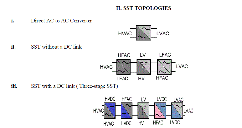 |
| The three stage topology offers some advantages over the other two, such as [1]; reduced size due to a high frequency transformer, power factor improvement is possible, multi-level converter topologies can be applied to get high voltage levels (e.g., 11 and 22 kV). It is the three stage topology which is most prevalent now and various potentials of the power electronic circuit involved, like reduced switch topology, are being studied and developed for better proficiency. |
III. LOSSES INVOLVED |
| For a given voltage and number of turns, increasing the frequency allows for decreasing the cross-sectional area of the core without bringing the core into saturation. The advantage of running an electrical system at 100 to 400 Hz rather than 50 Hz is that the power supplies are smaller and lighter. But this reduction in weight comes at the cost of power electronic devices. As we know the iron loss consists of two components; the hysteresis and the eddy current components [2]. |
 |
| Increase in copper loss due to skin effect is not significant up to certain level. |
| As per the available literature; Diameter of wire which see 10% rise in resistance (in mm) |
| d = 200/√f = 28 mm for 50 Hz = 20 mm for 100 Hz and = 10 mm for 400 Hz. |
| It is well known that the skin effect is more significant when the frequency is above 400 Hz (this is the reason aircrafts use 400 Hz supply) whereas our study is restricted to 100 Hz only. Hence the total losses are almost constant for the double the frequency. The interconnecting devices would enable full control of magnitude and direction of real and reactive power flow and could replace the archaic uncontrollable, voluminous and heavy, line frequency transformers. |
IV. DESIGN OF TRANSFORMER |
| Based on the standard formulae [3]-[5] and practical considerations, an excel spreadsheet has been generated. This should expedite the process of designing transformer with ease and accuracy for several other ratings. |
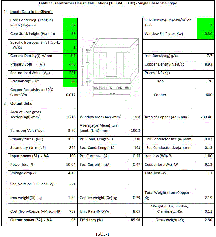
| A. The design of the 100 VA, 440/220 V transformer has been tested with the spreadsheet and the results are found to be similar to the calculated values as per the standard text books with an appreciable error of 1% in VA rating and efficiency. The developed excel spreadsheet is shown (table.1) |
| B. Estimation of Output rating with same core for double the frequency: |
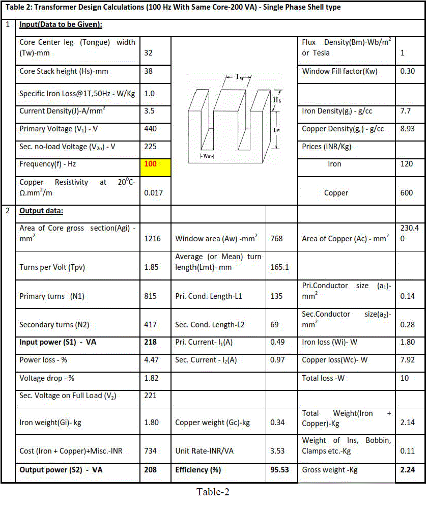
| The data has been fed to the developed spreadsheet and found that the output is doubled and concords with the calculated value (table.2). |
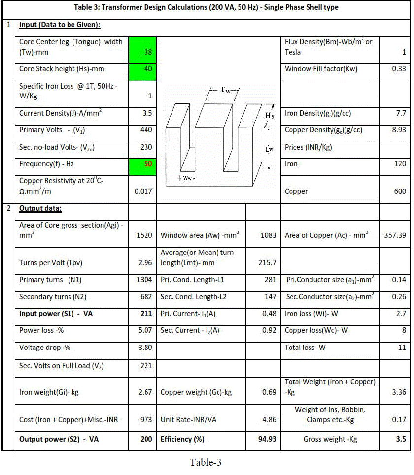
| C. The design of the 200 VA, 50 Hz (table.3) : |
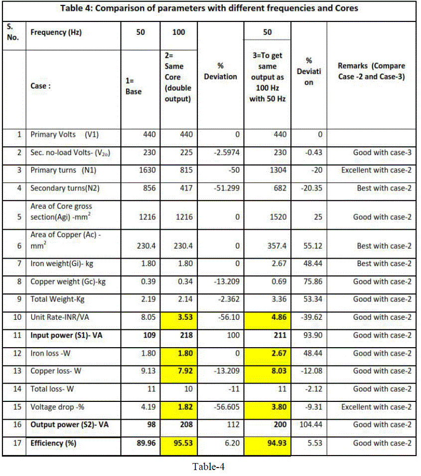
| D. Comparison of different designs : Shown in table-4. |
| E. Results : In spite of increase in the frequency, the core losses are reduced which is already mentioned earlier. The transformer’s no load current has been measured (hardware) and the results corroborate the above statement. Using a supply source of 440V, 50Hz the following currents are measured : |
 |
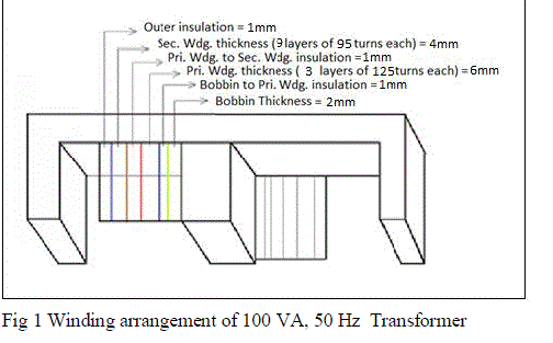
| F. Winding Arrangement : Fig 1 shows the Winding arrangement of 100 VA, 50 Hz transformer. |
 |
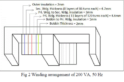
| Fig 2 shows the Winding arrangement of 200 VA, 50 Hz |
 |
V. CONCLUSION |
| From the comparison table, case-3 transformer offers slightly less efficiency and modest core loss. Whereas, case-2 transformer proposes the minimum voltage drop, better efficiency and least unit rate. Not to forget, the supplementary pros of using power electronics in the circuit in the SST paradigm. Also, the reduced no load or core losses substantiates the superior qualities of SST. Contemplating various parameters involved in the design and the practical considerations taken into account; case-2 i.e. 100 VA, 100 Hz transformer possess the attributes of a transformer that would fit perfectly in the future smart grid. |
ACKNOWLEDGEMENT |
| The authors would like to thank the School of Electrical Engineering (SELECT), VIT University, Vellore, Tamil Nadu for their continuous guidance and encouragement to carry out this work. |
References |
|
 |
 |
 |
 |