Keywords
|
| Microfluidics, Microchannel, Printed circuit board, Fabrication, Mechanism |
INTRODUCTION
|
| Microfluidics provides a design efficient optimization tool considering the numerical simulation of microfluidics essentially valuable in the microfluidic applications. The behavior of a particular system which is initially difficult to predict can be analyzed and studied using microfluidic systems which further requires the incorporation of the complexities of different factors such as channel geometry , fluids flow rate , diffusion coefficients and possible chemical interactions altogether into a numerical model. This Numerical modeling in turn can be used to visualize the complex flow phenomenon which otherwise is difficult to obtain experimentally [1]. |
| Microfluidic devices is distinguished from other devices by a fact that microfluidic devices essentially contains either one or more channel of small dimensions nearly less than 1 mm. This can be obtained by fabricating highly integrated devices that are capable of performing several functions on same substrate chip more precisely keeping in view an idea to fit „entire lab on a chip? [2] in a manner similar to micro electronic circuit integrates „entire computer on a chip. |
| A. Physics in Microfludic channels |
| In fluid dynamics the type of flow that occurs in a fluid while flowing through a microchannel is considered important to observe whether the flow in fluid is turbulent that is less orderly regime or laminar, the stream lined flow, when fluid flows through a micro channel. Reynolds number is used to characterize the flow of the fluid through a micro channel and is defined mathematically as: [1], [2] |
 |
| Where „L? is most relevant length scale; L= 4A/P, A is crossectional area of the channel and P is wetted perimeter of the channel, μ is the viscosity, p is the fluid density, Vavg is the average velocity of flow. |
| Micro Mixing indicates a physical process in which both stirring and diffusion of micro fluids occurs simultaneously. The low diffusive microfluids mix in two simultaneous stages first the stirring occurs in the material blobs are mixed without any diffusion of two fluids. Two different fluids when subjected to micro mixing, the random motion of liquid molecules occurs everywhere [3]. |
| Diffusion is defined as the spreading of particles due to their Brownian motion. The event occurs due to thermal energy. The simplest way of modeling diffusion is in one dimension. This is described by the following equation [4]: |
 |
| Where xRMS is the root mean square displacement of a particle in a time t., D is the diffusion coefficient of the particle in the surrounding medium [5]. |
| Surface tension is defined as a contractive tendency of the surface of a liquid which allows it to resist an external acting force since the behavior of the liquid depends on cohesion forces acting between similar molecules. The surface tension is determined by equation [6]: |
 |
| Where γ is surface tension (mN/m); u is average cohesive energy of a molecule; δ is characteristic dimension of a molecule and δ2 represents the effective surface area of molecule. |
| The dynamics of microfluids includes the factors such as viscosity of fluids, resistance of fluids i.e fluidic resistance and it also includes an account of capillary pressure when fluid flow in capillaries. |
| Capillary pressure of a flow depends on its capillary action which is the ability of a material to draw another material into it. Due to capillary action the amount of material drawn is called the height (h) of liquid, and is calculated as: |
 |
| Where γ is surface tension at liquid air interface in N/m; θ is contact angle at the surface in degrees, ρ is density in kg/m3; g is Gravitational force m/s2, r is Column radius in m.[4], [6], [7]. |
| B. Materials |
| The materials required for microfluidic device fabrication and flow investigations are: |
| 1) Substrate: The substrates used for fabrication may be Silicon and Glass Substrates, Metals and SOL Gels The choice of substrate depends upon the application requirement. Glass and silicon substrates are used when small channels are required to be fabricated in microfluidic system with high resolution and repeatability and can be integrated into clean room environments with ease. Sol gels are silicate based compounds formed by condensation of Si(OH)4 by loss of water [8]. It requires formation of Si-0 network by thin film and should not contain OH and SOG is prone to shrinkage. Metals are commonly used in MEMS fabrication and the commonly used metals are aluminum, titanium copper etc. but its fabrication requires expensive techniques such as micromachining etc. so an effort is used to fabricate microchannel using PDMS elastomer of desired width and resolution which is used for flow analysis of different salt solutions [9], [10]. |
| 2) PDMS i.e. Poly Di-Methyl Siloxane: It is commonly used in microfluidic applications under the product name as Sylgard184. PDMS becomes stable and inert when comes in contact with chemicals and is also glass fusible. PDMS often becomes an elastic solid forming a hydrophobic surface after it is activated or cross linked. This feature is the main reason that PDMS surface never get wetted by polar molecules such as water which otherwise can lead to hydrophobic contaminant absorption. PDMS is inert, nonflammable and transparent optically and is used by disposable devices due to its low cost and ease of use [10], [11]. This concludes that PDMS can be used with reusable SU-8 master mold there by forming a stable and reliable microfluidic soft lithography device [10], [12]. The elastomeric properties of PDMS also make it vulnerable to specific problems such as the problems due to pressure gradients or gravitational deformations that causes closing of channels [12]. Commonly used PDMS are PDMS RTV– 615 and Sylgard PDMS 184. PDMS RTV-615 is the preferred PDMS of S. Quake used in invention of microfluidic valve and observed to be the robust and easy to bond bilayer microfluidic devices but it is usually dirty and requires the adjustment of the bonding parameters on each purchase since the plasma bond strength varies according to the batch. On the contrary PDMS Sylgard 184 is observed to be cleaner PDMS used less for multi layer and it makes the bonding between two PDMS layers more difficult and oftenly used in mammalian cell cultures in microfluidic chips. |
| Dow and corning’s Sylgard 184 is the commonly used PDMS in the microfluidics. It is a two part system with mix ratio of cross linker agent Siloxane in 1:10 ratio. Any increase in this micro mix cross linker ratio increases the rigidity of the PDMS [11] where as its mechanical properties can be changed by changing cure cycle [14]. Mixing of PDMS in other materials alters its mechanical properties that aid in making novel features better or not obtained with conventional PDMS. |
| Advantages of PDMS for Microfluidic Device Fabrication |
| • Its Transparency at optical frequencies (240nm-1100nm) causes the observation of fluid in microchannels visually or under microscope possible [15]. |
| • It is biocompatible and has low auto fluorescence and sticks to glass substrates or other PDMS layer tightly using plasma treatments which aid in production of multilayer PDMS [16], [17]. |
| • PDMS can be coated on substrate with controlled thickness during crosslinking by using spin coats which forms multilayer devices there by integrating microvalves using deformation of channel since PDMS is also deformable. |
| • Relatively inexpensive than is based materials and can mold structures at high resolutions [18], [19]. |
| 3) Salt Solutions: To study the flow of solutions in the cylindrical microchannels we are using different salt solutions of FeCl2.. The objective of studying the ferrous and copper salts is that as we know that our blood vessels are cylindrical in shape and Hb which contains Iron flow through it. So we will study the flow of these salts. |
| • Salt Solution of FeCl2: The salt solution of FeCl2 of 0.5 molarity was prepared and estimated using the buffer calculator. The molecular weight of FeCl2 was 126.75gms. The FeCl2. Salt (31.685 gms) was added to a 500 ml of water poured in a beaker and stirred gently to obtain the salt solution of Iron. |
| C. Some other Materials |
| Wire: Wire of different widths were used as channel patterns. |
| Metal syringes: To inject salt solutions at inlet of the channel patterned on PDMS layer. |
| Digital camera: Records video of the flow of salt solutions for investigations. |
| D. Fabrication Techniques |
| Over the period of time different techniques are employed for the manufacture of the microfluidic devices. The different fabrication techniques used are: |
| i. Micro-machining |
| ii. M4 Technique |
| a. Micro End Milling |
| b. Micro Electrical Discharge Milling (Micro EDM) |
| iii. Plasma Enhanced CVD |
| iv. Replica Molding Photolithography |
| v. X-Ray Lithography |
| a. LIGA |
| vi. Lab on a CD |
| vii. Embossing |
| Here the combined approach of replica method of fabrication and electrolysis for the fabrication of microfluidic channels was employed. |
METHODOLOGY
|
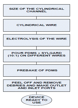
| The methodology involved in microchannel fabrication using PDMS elastomer Kit and study of the effect of shapes of channel on flow of different salt solutions is divided into three stages- stage 1 that involves the fabrication of microchannels in PDMS layer using wires of different dimensions, stage 2 includes the increase in depth of channel using electrolysis and stage 3 includes the flow analysis of two different salt solutions across different shaped microchannels to study the effect of different shapes on microfluidic flow. |
| A. Stage1: Channel Pattern Fabrication |
| PDMS Sylgard 184 kit of Dow Corning Corporation Ltd. was used as elastomer kit. Two chemicals base agent and curing agent were mixed in the mass ratio of 10:1 and poured into separate glass dish plates. PDMS, 110gm by weight was mixed with the 11 gms of sylgard to prepare a PDMS mix without existence of any air bubbles. Wires of different dimensions obtained through the electrolysis were taken and dipped into PDMS sylgard mixture. The PDMS Mix coated wires were baked at 1000C for 35 minutes. After baking, PDMS was peeled off and the wires were removed . The cylindrical channels of different widths were obtained as ready to use after removing the debris. These cylindrical microchannels were used for flow analysis of two salt solutions to study the effect of different microchannel widths on salt solution flow. |
| B. Stage 2: Electrolysis |
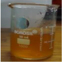
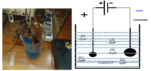
| Electrolysis process was used to increase the width of the wires to get different size of cylindrical microchannels. A copper wire was electrolysed to increase the thickness of the wire which inturn increases the width of the channel. As we know, in electrolysis copper sulphate dissociate to deposit on the wire which is used as the cathode and a pure copper is used as the anode. Hence, we obtain the different thickness of the wires by changing the time of electrolysis. The different chemical reactions involved in the electrolysis are: |
| CuSO4 ==> Cu (++) + SO4(-.-) (1) |
| Cu(++) + 2e (-) ==> Cu (2) |
| Cu ==> Cu (++) + 2e(-) (3) |
| C. Stage 3: Flow Analysis |
| The microchannels of different shapes were obtained and two salt solutions were prepare by mixing CuSO4 and FeCl2 with distilled water. These microfluidics solutions were made to flow across different microchannel shapes for further investigations. For flow analysis, we will flow the salt solution through the different cylindrical microchannels of different widths at different angle of inclinations. The Flow across microchannel was recorded using digital camera and investigated to study effect of width and inclinations of cylindrical channels on fluidic flow. |
RESULTS AND DISCUSSIONS
|
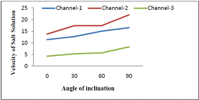
| The investigations were carried to study the effect of different shapes of microchannel on fluid flow The data obtained was compiled in Table 1. The results obtained were plotted as velocity plots (Fig. 7) revealing the velocity of salt solution in different channels-1,2 and 3 at varying inclinations. |
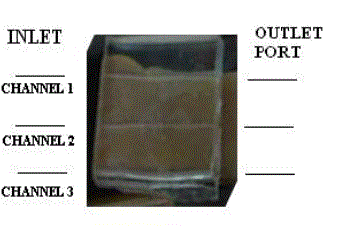
| A. Parameters of cylindrical channels |
| Length of the channel =3.3 cm |
| Diameter of Ist cylindrical channel = 0.5mm |
| Diameter of 2nd cylindrical channel = 0.25mm |
| Diameter of 3rd cylindrical channel = 1mm |
CONCLUSION
|
| Fabrication of the cylindrical microchannels in PDMS is carried out. Microchannels having diameters 0.25 mm, 0.5 mm, and 1 mm with length of 3.3 cm. FeCl2 solution is used to study the flow in the channel. Channels fabricated in PDMS are attached to the plat form and the platform is elevated from 0 degree to 90 degree with step size of 30 degree. Result reveals the behavior of the flow of solution in cylindrical channels. At right angle to the ground level gravity shows the prominent effect giving high velocity to the flow of the fluid in the channel. |
Tables at a glance
|
 |
| Table 1 |
|
| |
Figures at a glance
|
 |
 |
 |
 |
| Figure 1 |
Figure 2 |
Figure 3 |
Figure 4 |
 |
 |
 |
| Figure 5 |
Figure 6 |
Figure 7 |
|
| |
References
|
- Aleksandra Radenovic “Advanced Bioengineering Methods Laboratory Microfluidics Lab On Chip Microfluidics Lab On Chip” ,.
- Jo, B.-H.; Van Lerberghe, L.M.; Motsegood, K.M.; Beebe, D.J., “Three dimensional micro-channel fabrication in PDMS elastomer”, J.MEMS,Vol. 9, pp. 76-81, 2000
- Schuyler Vowell “Microfluidics : Effects of Surface Tension” ,Physics 486 March 12, 2009.
- Berg, H.C., “Random walks in biology.” 1983, Princeton: Princeton Univ. Press.142.
- G€unther and Michiel T. Kreutzer , “Fluid Dynamics in Microchannels, Multiphase Flow” in Axel Micro Process Engineering,Vol.1:Fundamentals, Operations and Catalysts Edited by V. Hessel, A. Renken, J.C. Schouten, and J.-I. Yoshida
- Schuyler Vowell “Microfluidics : Effects of Surface Tension” ,Physics 486 March 12, 2009
- Mackenzie J., Huang Q., and Iwamoto T., “Mechanical properties of ormosils” J. Sol-Gel Sci. Technol. 7, 151 (1996). doi:10.1007/BF00401034.
- Faivre, M., M. Abkarian, et al. (2006). "Geometrical focusing of cells in a microfluidicdevice: an approach to separate blood plasma." InBiorheology43(2): 147-59.
- Belanger, M. C.; Marois, Y. “Hemocompatibility, biocompatibility, inflammatory and in vivo studies of primary reference materialslow-density polyethylene and polydimethylsiloxane: a review.? In J Biomed Mater Res (2001), 58, 467-77
- Qin, Dong; Xia, Younan; Rogers, John A.; Jackman, Rebecca J.; Zhao, Xiao-Mei; Whitesides, George M. “Microfabrication ,microstructures and microsystems.” Topics in Current Chemistry (1998), 194(Microsystem Technology in Chemistry and Life Science).
- Irandoust, S., Andersson, B. “Liquid film in Taylor flow through a capillary”. In Industrial and Engineering Chemistry Research 28(1989), 1684–1688.
- Chan-Park, Mary B.; Zhang, Jun; Yan, Yehai; Yue, C. Y. “Fabrication of large SU-8 mold with high aspect ratio microchannels by UVexposure dose reduction.” Sensors and Actuators, B: Chemical (2004), B101(1-2), 175-182.
- Xia, Younan; Whitesides, George M. “Soft lithography”.in Annual Review of Materials Science (1998), 28
- Jung Y., Kar S., Talapatra S., Soldano C., Viswanathan G., Li X., Yao Z., Ou F., Avadhanula A., Vajtai R., Curran S., Nalamasu O., and
- Ajayan P. M., "Aligned Carbon Nanotube-Polymer Hybrid Architectures for Diverse Flexible Electronic Applications" in Nano Lett. 6, 413 (2006). doi: 10.1021/nl052238x.
- Chen L., Degenaar P., and Bradley D., “Polymer Transfer Printing: Application to Layer Coating, Pattern Definition, and Diode DarkCurrent Blocking” In Adv. Mater. (Weinheim, Ger.) 20, 1679 (2008). doi: 10.1002/adma.200702304.
- Piruska, A.; Nikcevic, I.; Lee, S. H.; Ahn, C.; Heineman, W. R.; Limbach, P. A.; Seliskar, “The autofluorescence of plastic materials andchips measured under laser irradiation.” In C. J. Lab Chip (2005), 5, 1348-54.
- Belanger, M. C.; Marois, Y. “Hemocompatibility, biocompatibility, inflammatory and in vivo studies of primary reference materials lowdensitypolyethylene and polydimethylsiloxane: a review.? In J Biomed Mater Res (2001), 58, 467-77
- GuilhemVelvéCasquillas ;“Pdms in biology research a critical review on pdms soft lithography for biological studies”.Hua, F.; Sun, Y.; Gaur, A.; Meitl, M. A.; Bilhaut, L.; Rotkina, L.; Wang, J.; Geil, P.; Shim, M.; Rogers, J. A. Nano letters (2004), 4, 2467-2472.
|