Nowadays energy management converter for electric drives are commonly being used for electric vehicles applications, due to various advantages, such as: nearly zero emission and energy recovery during braking operation. To fulfill these requirements converters with bidirectional power flow capabilities are required to connect the battery to the dc link of the motor drive system. A hybrid electric vehicle is required to function in three different modes namely: acceleration mode, normal (steady-state) mode and braking (regenerative) mode. In the present work open loop and closed loop operation of bi-directional dc-dc full bridge converter with a flyback snubber feeding a dc motor and its energy recovery due to regenerative braking has been demonstrated. The simulations are carried out using Simulink/ MATLAB 7.6.0 (R2009b) package.
Keywords |
| Flyback snubber, full-bridge bidirectional converter, Hybrid electric vehicle |
INTRODUCTION |
| Large numbers of automobiles around the world has caused and continue to cause serious problems in environment and
human life. Electric Vehicles (EVs), Hybrid Electric Vehicles (HEVs) and Fuel Cell Electric Vehicles (FCEVs) have
been typically proposed to replace conventional vehicles in the near future. The inherent flexibility of HEVs makes
them suited for personal transportation and military applications.
In renewable dc-supply systems, batteries are usually required to back-up power for electronic equipment.
Their voltage levels are typically much lower than the dc-bus voltage. Bidirectional converters for charging/discharging
the batteries are therefore required. Isolated bidirectional full bridge dc-dc converter has many advantages compared to
traditional dc-dc converter such as electrical isolation, high reliability and bidirectional energy flow. Some converters
are only suitable for stepping up or stepping down the voltage. This bidirectional converter is used for both stepping up
and stepping down the voltage. Therefore charging and discharging should be combined in one circuit topology.
For application where the output needs to be completely isolated from the input, isolated converters are employed. For
high power applications, full bridge topology is used. |
| The major concerns of an isolated bidirectional full bridge DC-DC converter with a flyback snubber include
reducing switching loss, reducing voltage and current stresses, and reducing conduction loss due to circulation current.
The full-bridge type topology has the following merits compared to the single-stage buck-boost type topology: |
| • Electrical isolation between input and output is guaranteed. |
| • Higher boost ratio can be implemented. |
| • System protection is possible when output stage short take place. |
| For these reasons a full bridge type topology has been chosen for the bi-directional DC-DCconverter. The objective of
the thesis is to introduce a fly back snubber to recycle the absorbed energy in the clamping capacitor. The fly back
snubber can be operated independently to regulate the voltage of the clamping capacitor; therefore, it can clamp the
voltage to a desired level. During start-up, the fly back snubber can be controlled to precharge the high-side capacitor,
improving feasibility significantly. The use of a bi-directional DC-DC converter with a flyback snubber fed dc motor
drive devoted to electric vehicles (EVs) application allows a suitable control of both motoring and regenerative braking
operations. |
| The objective of the paper is to compare bidirectional DC-DC converter with RCD, active clamp and flyback
snubber. From the comparison, to prove that flyback snubber in the bidirectional converter is better to reduce the
current stress and voltage spikes of the active switches.The Section I give the Introduction of the bidirectional
converter for hybrid electric vehicle. Section II is helpful to understand the background of related work. Section III
explains the simulations and its results and the lastsection IV concludes the paper and followed by the references. |
CIRCUIT DESCRIPTION |
| The proposed isolated bidirectional full-bridge DC–DC converter with a flyback snubber is shown in Fig. 1. The
converter is operated with two modes which are buck mode and boost mode. Fig.1 consists of a current-fed switch
bridge, a flyback snubber at the low-voltage side, and a voltage-fed bridge at the high-voltage side. Inductor
Lmperforms output filtering when power flows from the high-voltage side to the batteries, which is denoted as a buck
mode. On the other hand, it works in boost mode when power is transferred from the batteries to the high-voltage side. |
 |
| The clamp branch capacitor CC and diode DCare used to absorb the current difference between current-fed inductor
Lmand leakage inductance Llland Llhof isolation transformer Txduring switching commutation. The flyback snubber can
be independently controlled to regulate VCto the desired value, which is just slightly higher than VAB. Thus, the voltage
stress of switchesM1–M4 can be limitedto a low level.A bidirectional DC-DC converter has two types of conversions:
step-up conversion (boost mode) and step-down conversion (buck mode). In boost mode, switches M1–M4 are
controlled,and the body diodes of switches M5–M8are used as a rectifier. In buck mode, switches M5–M8 are controlled,
and thebody diodes of switches M1–M4 operate as a rectifier. |
| A. STEP UP OPERATION |
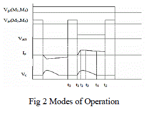
| First of all switches M1-M4 are turned on, so the primary side of the transformer is short circuited and therefore
VAB=0. Inductor, L is charged by the battery. At t1, M1& M4 remain conducting, so VAB is present. Clamping diode, Dc
continues to conduct until the current difference drops top zero at t2. Moreover D5 and D8 are conducting to transfer the
power. During this interval (iL-iP) flows into clamping capacitor. So clamp capacitor voltage, VC is rising at the interval
t1-t2 and ip= iL condition is reached. During t2 -t3, Dc stops conduction and flyback snubber starts to operate. Cc is
discharging and the flyback switch is turned on and the energy is stored in flyback snubber as flux. In the interval t3-t4
energy stored in the inductor is transferred to high voltage side. Over this interval, flyback snubber will operate
independently to regulate VC to VC(R). Energy stored in the transformer of the flyback snubber is transferred to the output
when flyback switch turns off.At t4, Vc has been regulated to VC(R) and the snubber remains idle. Over this interval the
main power stage is still transferring power from low voltage to high voltage side. It stops at t5 and completes a half
switchingcycle operation. |
 |
| B. STEP DOWN OPERATION |
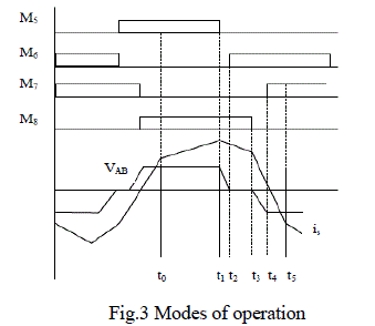
| During the time period t0-t1, switches M5 and M8 are on, while switches M6 and M7 are in the off state. High
side voltage is immediately exerted on the transformer and the whole voltage is exerted on the transformer causing
current to rise. With transformer current, is increasing linearly towards the load current at t1, switches, M1 and M4 are
conducting to transfer the power and the voltage across the transformer terminals on the current fed side changes
immediately to reflect the voltage from the voltage fed side.
At t1, switch M8 remain conducting, while switch M5 is turned off. Diode, D6 starts to conduct the
freewheeling leakage current. Transformer current reaches the load current level at t1 and starts to decrease during the
interval t1-t2 and voltage VAB starts to decrease. The clamping diode, Dc starts to conduct during this interval.
At t2, with diode, D6 conducting, switch, M6 can be turned on under ZVS. At t3, switch M6 remains conducting,
while switch, M8 is turned off. Diode, D7 then starts to conduct the freewheeling leakage current. |
| At t4, with the diode, D7 conducting, switch M7 can be turned on under ZVS. Over this interval, the active switches
change to the other pair of diagonal switches and the voltage on the transformer reverse its polarity to balance the flux
and to alleviate the transient voltage problem. It stops at t5 and completes a half switchingcycle operation. |
 |
| An isolated bidirectional full bridge DC-DC converter transformer converter had voltage spikes due to the
current difference between the current fed inductor and leakage inductance of the isolation transformer. This voltage
spike has been alleviated by the flyback snubber. The flyback snubber can be controlled to attain a soft start-up feature.
The current stress is reduced under heavy load conditions. This converter has also the advantage of increased reliability
and efficiency. |
SIMULATIONS |
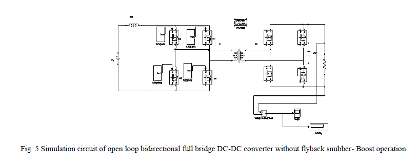
| The simulation of the proposed paper is carried out using MATLAB software. The open and closed loop
simulation of buck mode and boost mode is done separately. For open loop simulation, PWM pulses are given as the
gating signal. For closed loop simulation, a voltage and current feedback circuit is considered. The isolated
bidirectional DC-DC full bridge converter with and without flyback snubber is simulated. The battery fed drive for
electric vehicles using isolated bidirectional DC-DC converter with a flyback snubber is also simulated. The
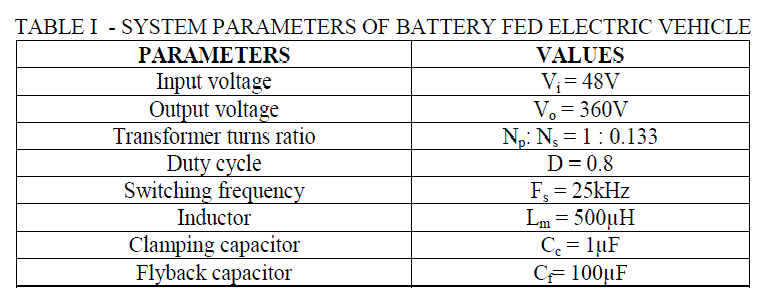
simulations are performed with following parameters and the design procedure is explained earlier. |
 |
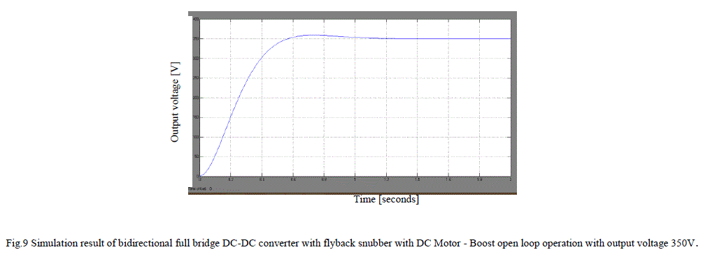
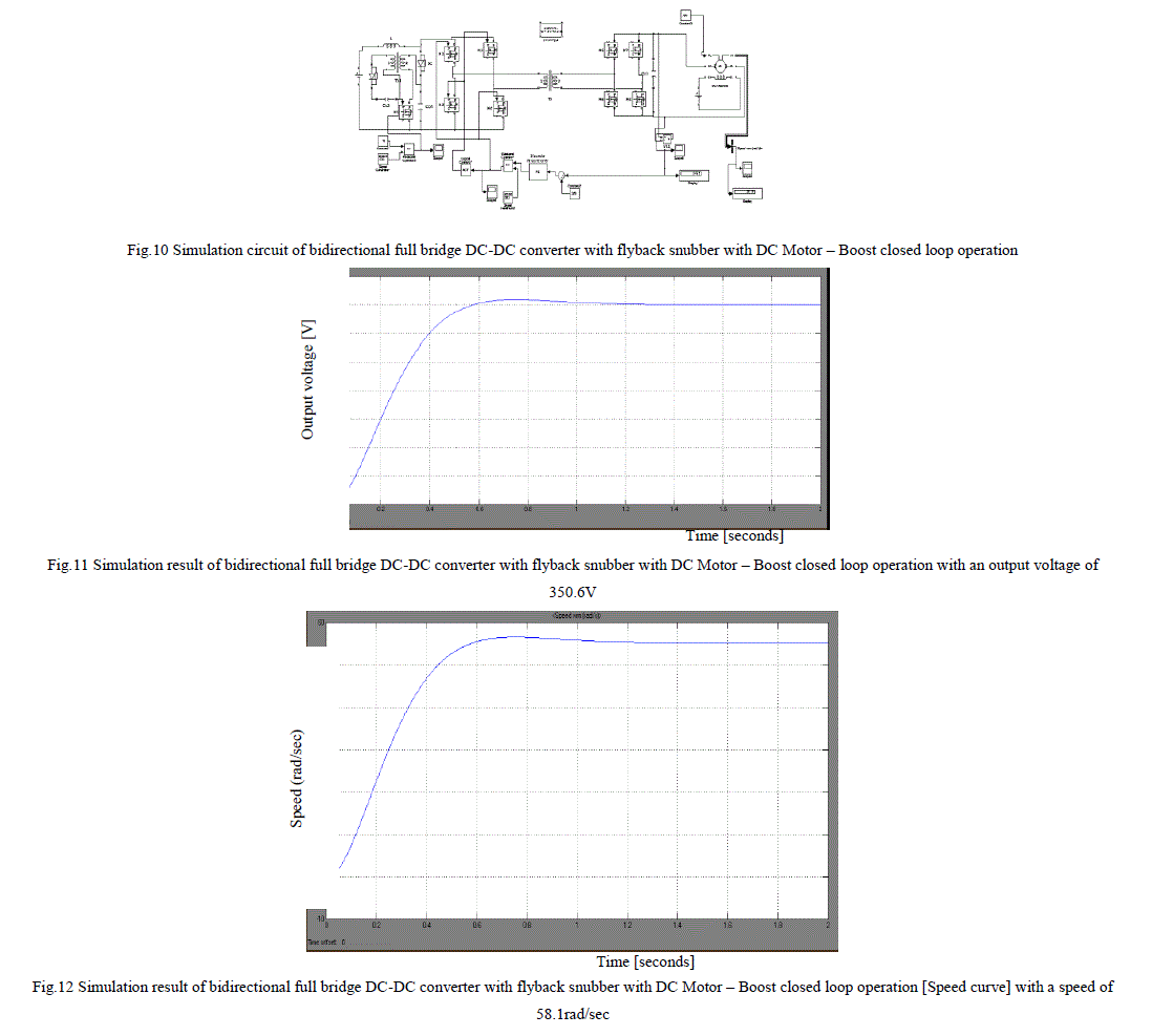
| A. SIMULATION RESULTS OF BOOST OPERATION |
 |
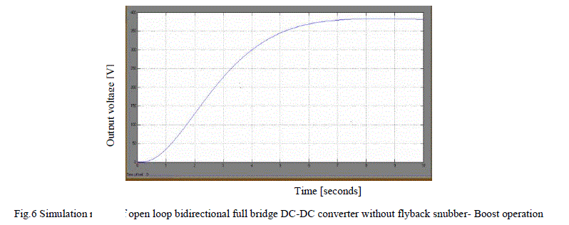 |
| We obtain an output voltage of 381.2V for open loop bidirectional full bridge DC-DC converter without flyback
snubber. |
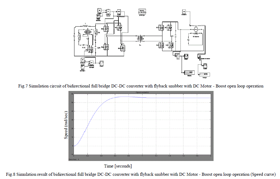 |
| We obtain a speed of 58.1rad/sec for of bidirectional full bridge DC-DC converter with flyback snubber-
Boost open loop operation. |
 |
 |
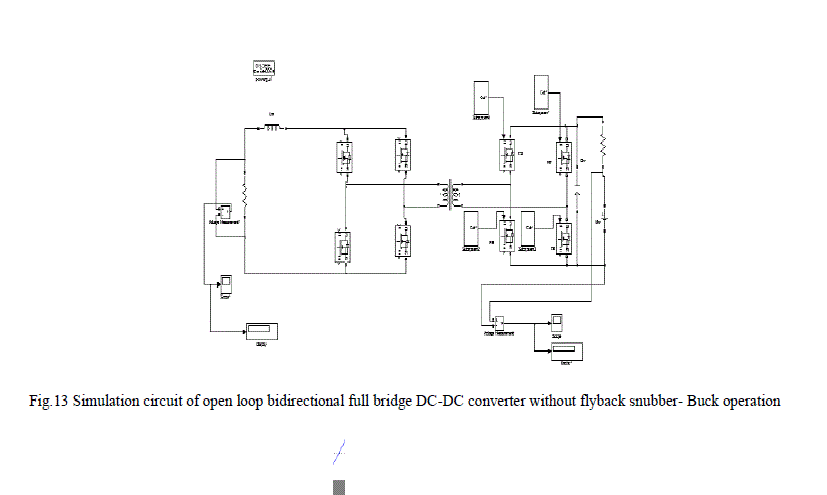
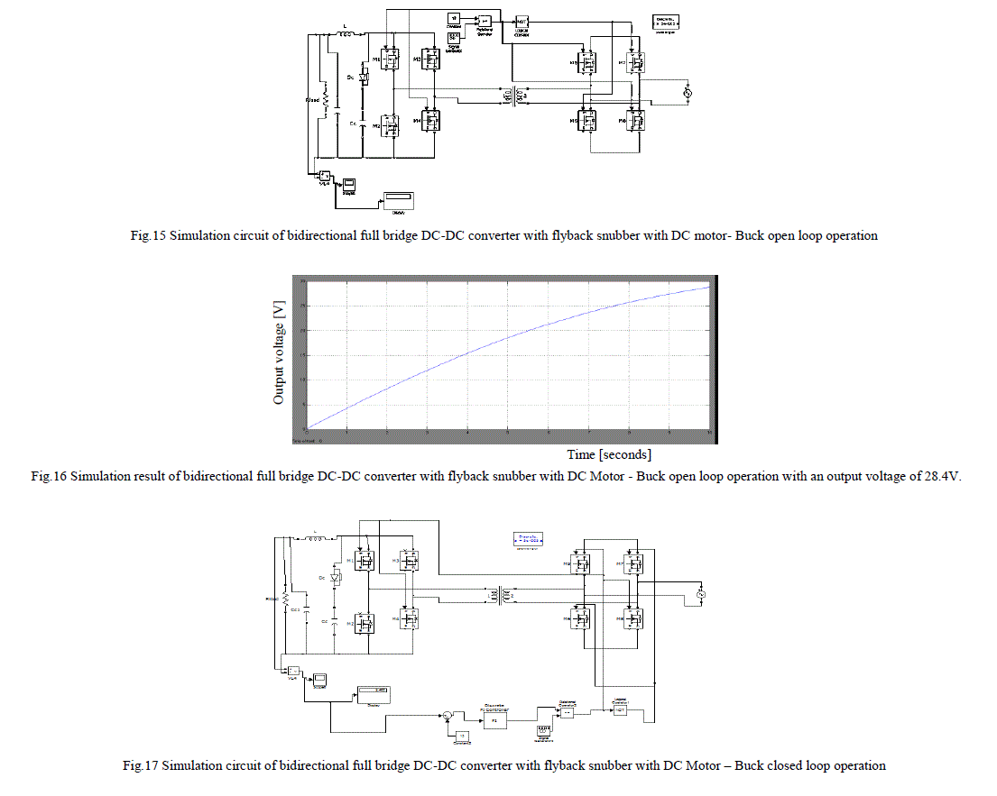
| B.SIMULATION RESULTS OF BUCK OPERATION |
 |
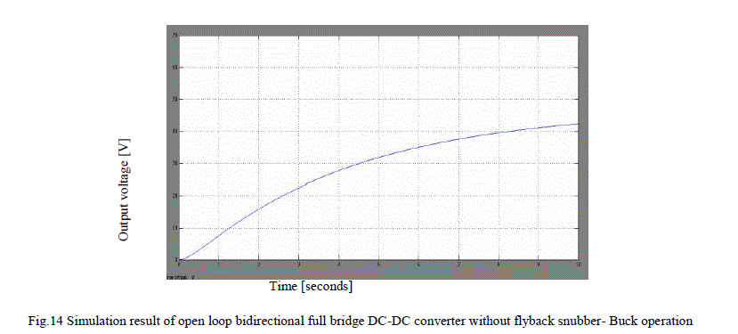 |
| We obtain an output voltage of 42.86V for open loop bidirectional full bridge DC-DC converter without flyback
snubber- Buck operation |
 |
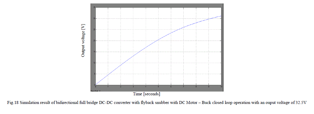 |
| The simulation results of open loop and closed loop control of isolated bidirectional DC-DC converter with
and without flyback snubber for various loads are done. DC motor as a load is used for the simulation in hybrid vehicle
application. |
CONCLUSION |
| Bidirectional dc-dc converters (BDC) have recently received a lot of attention due to the increasing need of systems
with the capability of bidirectional energy transfer between two dc buses. Apart from traditional application in dc motor
drives, new applications of BDC include energy storage in renewable energy systems, fuel cell energy systems, hybrid
electric vehicles (HEV) and uninterruptible power supplies (UPS). |
| An isolated bidirectional dc-dc converter with a flyback snubber is presented. The flyback snubber can
alleviate the voltage spike caused by the current difference between the current fed inductor and leakage inductance of
the isolation transformer, and can reduce the current flowing through the active switches. Since the current does not
circulate through the full bridge switches, their current stress can be reduced dramatically. The work demonstrates the
performance of a battery operated electric vehicle system and it shows satisfactory performance at different driving
condition. The proposed control technique with PI controller find suitable for this electric drive. |
ACKNOWLEDGMENT |
| The authors acknowledge gratefully for the support of Electrical and Electronics Department of AmalJyothi college
of Engineering, Kanjirappilly and the Electrical and Electronics Department of M A College of Engineering,
Kothamangalam |
References |
- T. Wu,, Y. Chu Chen, J. Yang, and C. Kuo, âÃâ¬ÃÅIsolated Bidirectional Full-Bridge DCâÃâ¬ÃâDC Converter With a FlybackSnubberâÃâ¬ÃÂ, IEEE Transactions PowerElectronics,Vol.23, pp 1915-1922, 2010.
- X. D. Xue, K. W. E. Cheng, and N. C. Cheung, âÃâ¬ÃÅSelection of Electric Motor Drives for Electric VehiclesâÃâ¬Ã Australasian Universities PowerEngineeringConference (AUPEC'08),Vol.56, pp198-208, 2008.
- K.Wang, F.C. Lee, and J.Lai âÃâ¬ÃÅOperation principles of bi-directional full-bridge DC-DC converter with unified soft-switching scheme and softstartingcapabilityâÃâ¬Ã International Journal of Engineering Science and Technology (IJEST), Vol. 3, pp 167-174, 2011.
- M. Rafiq, M. F. Hasan âÃâ¬ÃÅDesign and Analysis of 60 kW DC-DC Converter for Hybrid Electric Vehicle ApplicationsâÃâ¬ÃÂ.âÃâ¬ÃÂ, IEEE Transactions PowerElectronics, vol. 39, pp. 1881-1886, March 2010.
- P.Pany, R.K. Singh, R.K. Tripathi , âÃâ¬ÃÅBidirectional DC-DC converter fed drive for electric vehicle systemâÃâ¬Ã International Journal of Engineering,ScienceandTechnology, Vol. 3, No. 3, pp. 101-110,2011.
- O. GarcÃÆÃÂa, L.A. Flores, J.A. Oliver, J.A Cobos, and J. de la Pena, âÃâ¬ÃžBi-directional dc-dc converter for hybrid vehiclesâÃâ¬ÃÂ, IEEE Transactions PowerElectronics,vol. 27, no. 3, pp. 1881-1886, 2005.
- T. Bhattacharya, V. S. Giri, K. Mathew, and L. Umanand, âÃâ¬ÃÅMultiphase Bidirectional Flyback Converter Topology for Hybrid Electric VehiclesâÃâ¬ÃÂ,IEEETransactions Industrial Electronics, vol. 56, no. 1, pp. 78-84, 2009.
- O. C. Onar and A. Khaligh,âÃâ¬Ã A Novel Integrated Magnetic Structure Based DC/DC converter for Hybrid Battery/Ultracapacitor Energy StorageSystemsâÃâ¬ÃÂ,IEEE Transactions on SMART GRID, vol. 3, no. 1,pp. 296-307, 2012.
|