Keywords
|
| Fault tolerance, permanent magnet synchronous machine (PMSM), reliability, voltage source inverter (VSI). |
INTRODUCTION
|
| Generally industrial drives consists of many parts such as power electronic converter , a digital controller,feedback sensor and motorit. A fault in any one of the parts will stop the drive running or it may effects the drives performance. Some critical application such as power plant, railway locomotives, aerospace,automobiles ,etc.where the fault tolerant of a drive is very important . For an industrial processing plant a fault in single drive can result in trimenduos damage of meterials and machines. Follow- up cost due to fault can amount to huge sum.So the fault tolerant is the area of great interest for modern drive solution. |
| To short out this problem various theory are proposed as for example according to some topology For proper operation with some topology, the neutral point of the motor or faulted leg has to be connected to the midpoint of the dc voltage link, created using the use of two capacitors . In this type of control, the inverter should be over-rated so as to produce the rated torque output. A valid alternative that does not require the availability of the dc link midpoint is proposed in , at the cost of using additional components. Though it needs addi-tional components, it gives 100% output at postfault operation, without overloading the inverter. However, this topology uses auxiliary capacitors and fast-acting semiconductor fuses to iso-late the faulted leg. The rating and the size of the capacitors increase with the rating of the inverter. The presence of fuses increases the cost of the inverter and also dc bus parasitic in-ductance. |
| In case of a fault in converter or ma-chine, the remaining motor can continue to operate. Reduction of torque in case of a fault in converter or ma-chine, the remaining motor can continue to operate. Reduction of torque in case of a fault in one phase of the drive can be com-pensated by over-rating the remaining healthy phases. A modu-lar parallel redundant system has been proposed in , where two complete setup of drive systems are arranged on a common shaft and all the motor phases are driven by independent single-phase inverters. A fault in any set of the drive reduces the output power to 50%. A fault-tolerant inverter topology similar to has been proposed in but using the back–to-backconnected IGBTs for isolating the faulted leg. These IGBTs increase the cost of the inverter and also losses in the inverter are increased due to on-state resistance of the isolating devices. |
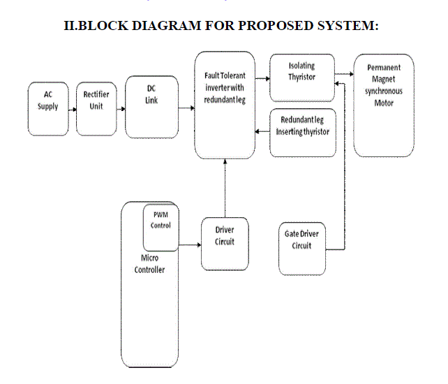
| The all above proposed theory increase the cost ,losses and decreases the performance. This paper proposes sum modification to the existing topology such that there is no compromise between the cost and performance of the inverter.Back to back connected thyristor are used in place of electromachenical relays. |
BLOCK DIAGRAM FOR PROPOSED SYSTEM
|
 |
| Three phase voltage-fed PWM inverters are recently showing growing popularity for multi-megawatt industrial drive applications. The main reasons for this popularity are easy sharing of large voltage between the series devices and the improvement of the harmonic quality at the output as compared to a two level inverter. In the lower end of power, GTO devices are being replaced by IGBTs because of their rapid evolution in voltage and current ratings and higher switching frequency. The Space Vector Pulse Width Modulation of a three level inverter provides the additional advantage of superior harmonic quality and larger under-modulation range that extends the modulation factor to 90.7% from the traditional value of 78.5% in Sinusoidal Pulse Width Modulation. |
| An adjustable speed drive (ASD) is a device used to provide continuous range process speed control (as compared to discrete speed control as in gearboxes or multi-speed motors). An ASD is capable of adjusting both speed and torque from an induction or synchronous motor. An electric ASD is an electrical system used to control motor speed. ASDs may be referred to by a variety of names, such as variable speed drives, adjustable frequency drives or variable frequency inverters. The latter two terms will only be used to refer to certain AC systems, as is often the practice, although some DC drives are also based on the principle of adjustable frequency. |
SYSTEM DISCRIPTION
|
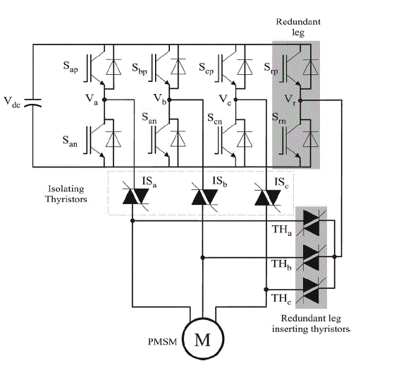
| The fault -tolerant inverter of this type consists of four legs, with one leg as redundant. The redundant leg is normally not used when the standard three legs are working without any fault. Back-to-back-connected thyristors (ISa , ISb , and ISc ) are connected between output terminals of the inverter (Va , Vb , and Vc ) and corresponding motor phases. These thyristors are used as isolating switches of faulted leg. Additional three thyristors (THa , THb , and THc ) are connected between the out-put terminal of redundant leg (Vr ) and motor phases . |
| The rating of the thyristors is the same as that of the IGBTs. During the normal operation, isolating thyristors (ISa , ISb , and ISc ) are always turned ON, which may cause undesired conduc-tion losses. |
| Different faults that can affect the drive’s operation are as follows: |
| 1) single-IGBT open-circuit fault, |
| 2) single-IGBT short-circuit fault, |
 |
| Operation for the single IGBT open circuit fault: |
| standard three-phase two-level VSI with an open switch fault (Sap open) controlling an ac machine. When one of the IGBT does not turn ON, in the case of motor operation, current in that phase is zero for a half-cycle, either positive or negative half-cycle depending on whether it is upper IGBT or lower IGBT. |
| Different methods for detecting the open-circuit fault of the IGBT are available in the literature . Some methods are based on the using voltage sensors and some are based on software techniques without using any additional hardware . According to , the open-circuit fault of the IGBT can be detected by inserting voltage sensors at desired locations. Depending on the location of the voltage sensor inserted, the fault detection techniques can be classified as follows: |
| 1) inverter pole voltage measurement, |
| 2) machine phase voltage measurement, |
| 3) system line voltage measurement, |
| 4) machine neutral voltage measurement. |
| Though these methods have short fault-detection time, they need extra voltage sensors for fault detection. To overcome the aforementioned problem, in some papers, software-based tech-niques have been suggested . Similarly different types of fault detection method is used.in this paper no special fault detection method is adopted inorder to test the inverter performance , aworst case is assumed where it takes atleast one current cycle to detect thefault. |
 |
| 2.Oreration for the single IGBT short circuit: |
| For a fault-tolerant drive, it is essential to isolate the faulted phase as fast as possible and to activate the redundant leg in order to resume normal operation. A short-circuit fault in the IGBT may be due to the malfunctioning of the gate drive or permanent damage in the IGBT. Fig. shows the standard VSI with an IGBT short-circuit fault (Sap shorted). A standard Vce desaturation-based fault detection is used for the IGBT short-circuit fault detection . |
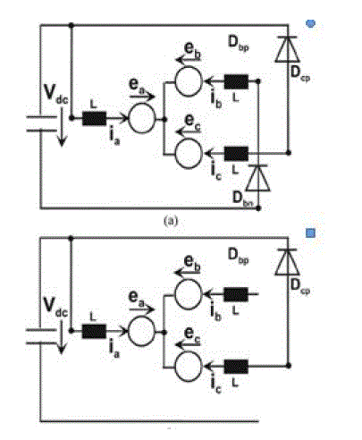
| As soon as the IGBT short-circuit fault is detected, all the IGBTs are turned OFF by hardware protection. Now for the case of IGBT permanent damage, corresponding phase is per-manently connected to the dc link positive bus or negative bus depending on upper IGBT or lower IGBT is damaged. As long as the machine is running, current flows through the shorted IGBT and remaining free wheeling diodes of the inverter. F the standard VSI after the upper IGBT (Sap ) is short cir-cuited and hardware protection turns OFF all the other IGBTs. Depending on the instance of fault in a current cycle, fault cur-rent in that corresponding phase may take a lot of time to reach zero crossing in order to isolate the faulted phase leg. Depending on the parameters of drive, load, and operating point, sometimes this short-circuit current could be unidirectional . But for disturbance-free operation or for negligible disturbance of drive operation, the isolation of the faulted phase should be fast. In order to achieve the aforementioned requirement, a turn-OFF command is also issued to all the isolating thyristors (ISa , ISb , and ISc ), which facilitates in bringing the short-circuit current to zero. In what follows, the provided theoretical analysis shows that by giving a turn-OFF signal to all the isolating thyristors, current in the faulted phase reaches zero crossing. With the short-circuit fault on the IGBT Sap , phase “a” is permanently connected to dc link positive bus. If current is in the negative half-cycle when the fault occurred, as the phase is permanently connected to the positive dc bus after the fault, current tend to Short circuit IGBT |
| When the Sap short-circuit fault occurs in sec3, initially, ia and ib are positive, and ic is negative. After turning OFF all healthy IGBTs by hardware protection, the remaining current paths are shown in Fig. For a symmetrical machine, we get |
 |
| The slope of ib is strongly negative and ib will reach zero fast. As the gate signals for thyristor “ISb ” are blocked, the current remains at zero. After this, the current path shown in Fig. 5(b) exists and the equation is |
 |
| In Sec3, ea is positive and ec is negative so the slope of ia is negative, which brings ia to zero, i.e., all currents are zero. But for high current at low speed (standstill) with low or zero EMFs, |
| the time to reach zero current will be long until the energy stored in the inductances of the machine is dissipated. |
 |
| EXPERIMENTAL RESULT: |
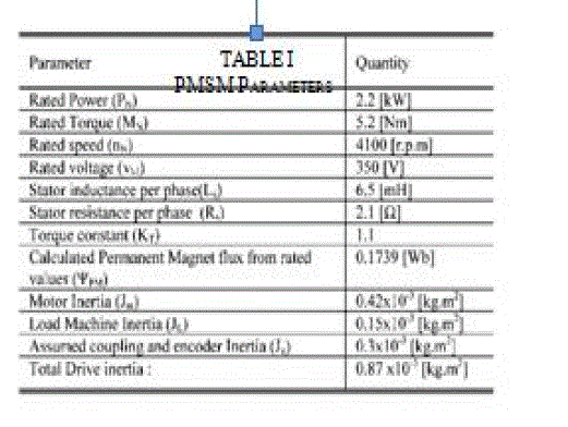
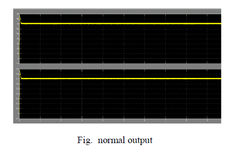
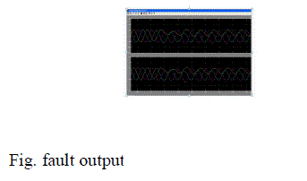
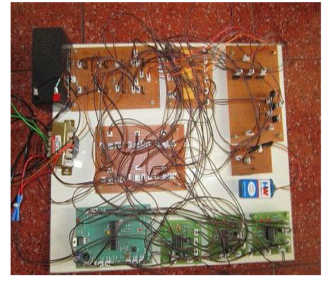
| A laboratory prototype has been built for testing the fault-tolerant inverter driving a field-oriented controlled PMSM. The PMSM is coupled with another PMSM, which is used as a load machine. A three-phase variable resistance is connected at the output terminals of the load machine which provides the re-quired load torque. The control algorithm is implemented in a Texas Instruments based F2812 fixed-point digital signal processor (DSP) evaluation board. A fault-tolerant controller was presented in Privious paper, but this is not the subject of this paper. Gen-eration of command signals for the converter, data acquisition, fault insertion, and fault compensation is done through software written in “C” language. All necessary variables are stored in the external memory of the DSP during control implementation and are later plotted using MATLAB. IGBTs are used as main switching devices and thyristors are used for isolating the fault leg. Results are produced for both the uncompensated fault and the compensated fault case. The uncompensated fault case ex-plains the behavior of the standard two-level inverter after the fault and the compensated case is the fault-tolerant inverter’s response to different faults. PMSM parameters are presented in Table I and a picture of the experimental setup is included in the appendix. |
 |
| SIMULATION OUTPUT: |
 |
 |
 |
| RESULT |
| Standard two-level three-phase inverter consists of only three legs but the fault-tolerant inverter of this topology consists of four legs, with one leg as redundantThe redundant leg is normally not used when the standard three legs are working without any fault.Back-to-back-connected thyristors are connected between output terminals of the inverter and corresponding motor phases.These thyristors are used as isolating switches of faulted leg. Additional three thyristors are connected between the output terminal of redundant leg and motor phases. |
| Advantage: |
| • Continuous operation of the motor can be achieved with help of redundant leg. |
| • The damage of motor drives can be prevented during fault condition |
CONCLUSION
|
| This paper has presented a fault-tolerant VSI that can compen-sate both short-circuit and open-circuit faults in the switching devices. It is simple in construction, modular, and easy to con-trol. Experimental results show that the compensation strategy is fast enough such that there is negligible disturbance in the drive operation. Results show that thyristors can successfully isolate the faulted leg in all the fault cases. The postfault performance of the machine is the same as the prefault, and the postfault con-trol algorithm is the same as prefault. The achieved results show that this inverter can fit in much safety critical and industrial applications where fault tolerance is of prime importance |
References
|
- O. V. Thorsen and M. Dalva, “A survey of the reliability with an analysis of faults on the variable frequency drives in industry,” in Proc. Conf. Rec. 6th Eur. Power Electron. Appl. Conf., Sevilla, Spain, 1995, pp. 1033–1038.
- H. Schwab, A. Kl¨onne, S. Reck, and I. Ramesohl, “Reliability evaluation of a permanent magnet synchronous motor drive for an automotive application,” in Proc. Conf. Rec. Eur. Power Electron. Appl., Toulouse, France, 2003.
- UTE C 20-810 RDF 2000, Reliability Data Handbook, Union technique de L’Electricite, Jul. 2000.
- B. A. Welchko, T. A. Lipo, T. M. Jahns, and S. E. Schulz, “Fault tolerant three-phase ac motor drive topologies: A comparison of features, cost, and limitations,” IEEE Trans. Power Electron., vol. 19, no. 4, pp. 1108–1116, Jul. 2004.
- T. H. Liu, J. R. Fu, and T. A. Lipo, “A strategy for improving reliability of field-oriented controlled induction motor drives,” IEEE Trans. Ind. Appl., vol. 29, no. 5, pp. 910–918, Sep./Oct. 1993.
|