The paper aims to design and develop a five phase permanent magnet BLDC for aerospace applications. A radial flux, surface mounted permanent magnet BLDC motor was designed with 33 slots and 10 poles and the analysis was carried out using finite element method in COMSOL Multiphysics. Hall sensors were used for getting the position of the rotor for proper energisation of the stator winding. The cogging torque obtained is less than 1% of the actual torque due to the fractional slot pitch windings which is verified by the simulation. According to the design a five phase motor was implemented and validated that the resistance and inductance value obtained during the analysis was found matching with the developed motor.
Keywords |
| Cogging Torque, Surface mounted PM, Multi phase, Finite Element Analysis |
INTRODUCTION |
| The multiphase motors are gaining popularity due to its increased advantages over three phase motors [1],[2].
During the event of failure of one or more phases, the remaining healthy phases let the motor to operate properly with
multi phases [3]. For aerospace applications, high reliability and fault tolerance of the machine is strongly desired due
to the safety concerns. Five- phase machines show a good compromise between the reduction of the power per phase
and the increased complexity of the power electronics linked to a high number of phases [4]. |
| Different rotor configurations are available for PMBLDC motor namely surface mounted PM design with interior or
exterior rotor, interior PM design with buried magnets etc. as in [5], each having specific strengths and weaknesses.
Among these the radial-flux, surface mounted type is commonly used for its simplicity for manufacturing. A five
phase, radial-flux, surface mounted permanent magnet BLDC motor was selected for the analysis due to its wide scope
applications. The factors affecting the design and its considerations can be seen in section II. The motor design is
broadly explained in section III. Finite Element Method using COMSOL Multiphysics is used as the analysis tool. |
DESIGN CONSIDERATIONS |
| For the design of a motor various factors have to be taken into consideration. The permanent magnet in the PM
BLDC motor allows greater ease in manufacturing of the motor. Surface mounted permanent magnets [6] can provide
the greatest magnetic field because nothing is blocking the field path. |
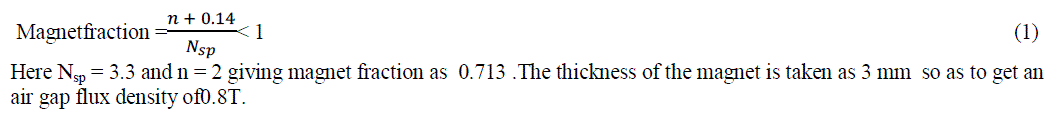
| A. Selection of magnets |
| The rare earth magnets having high coercive force, high remnant flux density, low permeability, overload capacity,
high energy product and virtually no aging are preferred for torque motors. To reduce the size of the motor and
considering the operating environments, SmCo5 magnets have been selected with the highest energy density, saturation
flux density, thermal capability and coercive force. |
| B. Selection of air gap |
| Smaller the air gap, higher the torque of the motor and also the efficiency, provided the material parts are not
saturated. Here the air gap length is chosen as 0.6 mm. |
| C. Selection of number of magnets and slot: |
| Different magnet and slot combination are available for same motor. Fractional slot winding is chosen in order to
reduce ripple and cogging torque which is mostly common in torque motors. Larger number of magnet increases the
core losses for the same speed. As an optimum value 10 poles was found suitable for this particular air gap diameter.
Also 33 slots have been chosen in order to have enough width for the teeth so that it does not get saturated. |
MOTOR DESIGN |
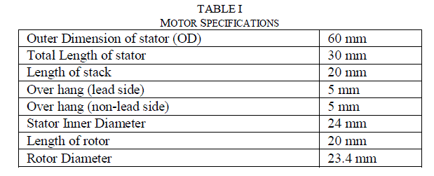
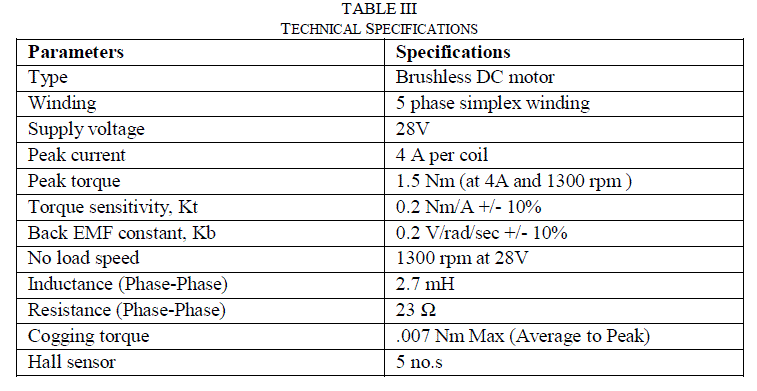
| From the design considerations [7] as given in section II the motor has been designed with the following
specifications as in table I. The technical specifications are listed in table II. |
 |
 |
| A. Dimensions of Magnet: |
| The length and width of the magnet is chosen as 20 mm and 10.3 mm respectively. |
 |
| B. Number of turns per phase: |
| The motor model is as shown in fig.1(a) which shows the slots in the stator and the permanent magnets on the rotor.
The torque equation for a poly phase motor is given by T. J. E Miller as in equation 2. |
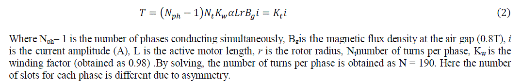 |
| Where Nph– 1 is the number of phases conducting simultaneously, Bgis the magnetic flux density at the air gap (0.8T), i
is the current amplitude (A), L is the active motor length, r is the rotor radius, Ntnumber of turns per phase, Kw is the
winding factor (obtained as 0.98) .By solving, the number of turns per phase is obtained as N = 190. Here the number
of slots for each phase is different due to asymmetry. |
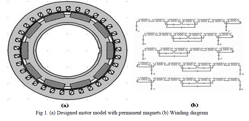 |
| With 33 slots and 10 poles the pole pitch is 3 slots/pole. Accordingly the winding diagram for the five phase
motor with the required specifications can be drawn as in fig.1(b). From the winding diagram it canbe seen that the
phases A, D and E is having 7 slots/phase and phases B and C have 6slots/phase. Therefore the no. of turns per slot for
each phase has been obtained as 27, 31, 31, 27 and 27 for phase A, B, C, D and E respectively. The back EMF can be
expressed by the equation 3. |
 |
FINITE ELEMENT ANALYSIS |
| COMSOL Multiphysics [8] is a powerful interactive environment for modelling and solving all kinds of
scientific and engineering problems based on partial differential equations. When solving the models, it uses the proven
finite element method (FEM). The software runs the finite element analysis together with adaptive meshing and error
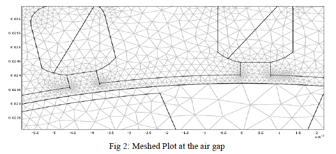
control using a variety of numerical solvers.Rotation is modelled using a deformed mesh application mode (ALE), in
which the centre part of the geometry, containing the rotor and part of the air-gap, rotates with a rotation transformation
relative to the coordinate system of the stator. As the rotor and the stator are drawn as two separate geometry objects,
the rotation of the deformed mesh is defined by the transformation given by equation 4 and the meshed plot at the air
gap can be seen as in fig 2. Finer the mesh [9] more accurate the results will be, though it takes more time for
simulation. |
 |
 |
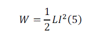
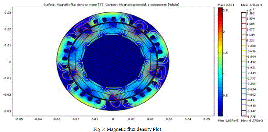
| An important design parameter is the calculation of inductance value of the conductor. Using COMSOL,
inductance value could be calculated in two ways namely: Energy method and virtual work method. In both these cases
magnetic flux density is kept zero to avoid the flux variation due to magnets.The magnetic flux density plot is as shown
in fig.3 which shows the variation of magnetic flux density at all points. In energy method the magnetic energy density
is obtained from the sub-domain integration using the expression of energy density. The inductance can be calculated
with the static solver using the equation given by equation 5. Here the current is taken in the milli ampere range. |
 |
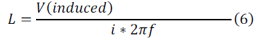
| Using the method of virtual work the analysis is done in time dependent transient mode and is based on the
fundamental Ohm’s Law (Equation 6). The currents in the stator windings are expressed as either the function of sine
and cosine terms and the induced voltage is plotted to obtain the inductance. |
 |
 |
| The torque is computed in COMSOL using the Maxwell’s stress tensor method [10] given by |
 |
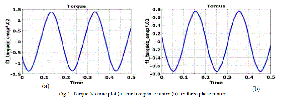 |
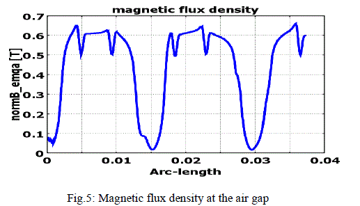
| A torque of 1.2 Nm is obtained with this designed five phase motor. A conventional three phase motor have yielded
less torque (0.75 Nm) for the same number of turns and current. An average value of 0.6 T is obtained as the magnetic
flux density at the air gap as is seen in fig.5. The dips in the wave are due to the slotting. |
 |
| Various voltage waveforms are plotted as in fig.6 which shows that a back EMF voltage of 28 V is obtained
when measured across the non-adjacent phases (Vac).The voltage between the adjacent phases (Vab) and also the
individual phase voltage (for Phase A) is also plotted. |
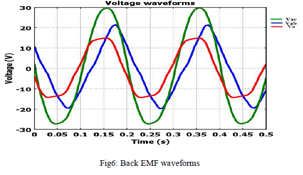 |
| The generated voltage is computed as the line integral of the electric field, E along the winding. i.e. it is obtained by
taking the average z component of E field for each winding cross section and multiplying it by the axial length of the
rotor, and taking sum over all winding cross sections (Fig.6). |
 |
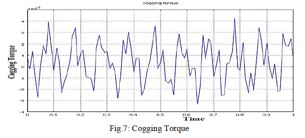
| Cogging torque is one of the major problems of a permanent magnet motor. With the specifications listed above
cogging torque profile should have 330 cycles per second.The cogging torque profile has been plotted as seen in fig.7,
which varies from 0.004Nm to -0.003Nm. There is considerable reduction in the cogging torque, i.e. less than 1 % of
the rated torque due to the fractional slot pitch winding. |
 |
HALL SENSOR PLACEMENT |
| BLDC motors use electronic instead of mechanical commutation to control the power distribution to the motor.
Latching Hall-effect sensors, mounted in the motor, are used to measure the motor’s position, which is communicated
to the electronic controller (microcontroller platform) to spin the motor at the right time and right orientation. These
Hall-effect sensors are operated by a magnetic field from a permanent magnet, responding to South and North poles.
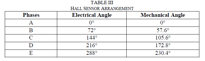
The electrical angle, θe and mechanical angle, θm can be related by the equation 10. |
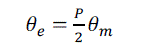 |
| Where p is the number of poles. Since themotor is having 10 poles, 360° mechanical i.e. one rotation, correspond to 5 x
360° electrical. The five-phase winding are electrically separated by 72°. So 72 electrical degrees is equivalent to 14.4°
mechanical. For this configuration the hall sensors for each phase are aligned at specificmechanical angles, which yield
a separation of 72 electrical degrees.A3187LUA hall sensor is used and is placed on Bakelite ring with the mechanical
angle as in table III. |
 |
EXPERIMENTAL RESULTS |
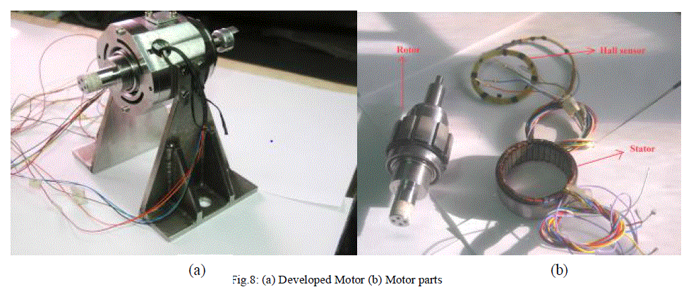
| The developed five phase PM BLDC motor with the stator and rotor along with the hall sensor ring is placed inside a
casing and the whole assembly is as shown in fig.8(a) with its various parts as in fig 8(b). After the completion of
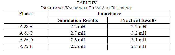
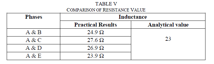
winding process, the inductance and resistance value is measured and is compared with that obtained during the
simulation. The table IV and table Vshows that the inductance and resistance values obtained analytically and
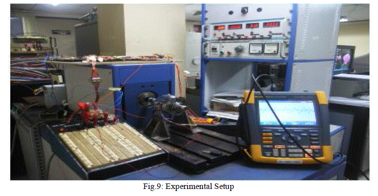
practically. It can be inferred that both the values match. The experimental set up using a dynamometer is as shown in
fig.9. |
 |
 |
 |
 |
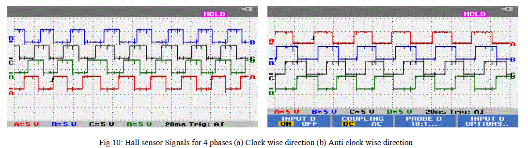
| The hall sensor signals as obtained with four phases are as shown in fig.10 while running in clock wise as well as in
anticlockwise direction. |
 |
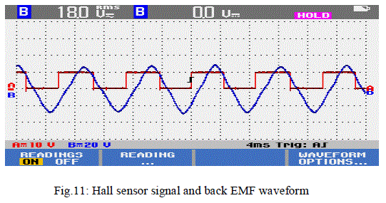
| The back EMF voltage at various speeds are noted and tabulated in table VI. The fig.11 shows the hall sensor and back
EMF of phase A at 1300 rpm. |
 |
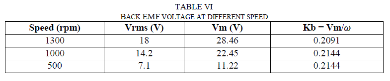 |
| From the table it is clear that the Kb value is approximately 0.2 meeting the specification as in tableII.The square
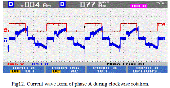
current waveform at phase A during clock wise rotation is as shown in fig.12. |
 |
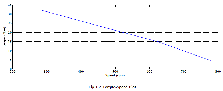
| The torque values have been noted for different speeds when load is applied and is plotted as shown in fig.13. |
 |
CONCLUSION |
| A five phase radial flux, surface mounted permanent magnet BLDC motor has been designed for servo
applications. The selection of materials is based on optimum value so as to obtain minimum size and weight. The
analysis has been done using finite element method in COMSOL Multiphysics. A motor has been developed based on
the design and the experimental results validate the simulation results. The resistance and inductance values obtained
analytically and practically were found matching. The fractional slot pitch winding is employed (33 slot, 10 pole),
reduced the cogging torque considerably which is less than 1 % of the rated torque. Due to the increased number of
phases the torque obtained is more when compared to the conventional three phase motor having same number of turns
and current. |
References |
- Ji, W. Song, and Y. Yang, âÃâ¬ÃÅOverview on application of permanent magnet brushless DC motorâÃâ¬ÃÂ, Electrical Machinery Technology, vol.40, pp.32- 36, Feb. 2003.
- L. Parsa, âÃâ¬ÃÅOn advantages of multi-phase machines", in Proc. IEEE Ind. Electron. Soc. Annu. Conf., pp. 1574 -1579, Nov. 2005.
- M. Villani, M. Tursini, G. Fabri, L. Castellini, âÃâ¬ÃÅFault-Tolerant PM Brushless DC Drive for Aerospace Application", XIX International Conference on Electrical Machines -ICEM, Rome, 2010.
- Xiaoyan Huang, Andrew Goodman, Chris Gerada, Youtong Fang and Qinfen Lu, âÃâ¬ÃÅDesign of a Five-Phase Brushless DC Motor for a Safety Critical Aerospace Application", IEEE transactions on industrial electronics, Vol. 59, No. 9, Sept. 2012.
- F. Libert, J. Soulard, âÃâ¬ÃÅDesign Study of Different Direct-Driven Permanent-Magnet Mo-tors for a Low Speed Application", Division of Electrical Machines and Power Electronics, Royal Institute of Technology , pp. 1 âÃâ¬Ãâ 6
- R.P. Praveen, M.H. Ravichandran, V.T. SadasivanAchari, Dr. V.P. Jagathy Raj, Dr. G. Madhu, Dr. G.R. Bindu, and Dr. F. Dubas, âÃâ¬ÃÅOptimal Design of a Surface Mounted Permanent-Magnet BLDC Motor for Spacecraft Applications", Proc. OF ICETECT , 2011.
- J. R. Hendershot Jr., T.J.E. Miller, Design of Brushless Permanent magnet motors,Magna Physics publishing and Clarendon press- Oxford, 1994
- COMSOL Multiphysics user manuel
- Yuqi Rang, HaoXiong, Qiang Wu, GuangweiMeng , Huaishu Li, Libing Zhou , âÃâ¬ÃÅFEM Simulation and Harmonic Torque Analysis of Six-Phase BLDC Motor ", IEEE Conf. , AIMSEC , pp. 3984 - 3987, Aug. 2011
- Why do infinite Element Analysis-NAFEMS
|