ISSN ONLINE(2278-8875) PRINT (2320-3765)
ISSN ONLINE(2278-8875) PRINT (2320-3765)
Anet Jose1 and ShanifaBeevi S2
|
| Related article at Pubmed, Scholar Google |
Visit for more related articles at International Journal of Advanced Research in Electrical, Electronics and Instrumentation Engineering
This paper focuses on the direct torque control (DTC) of induction motor drive (IMD) using multiple Fuzzy Logic Controller (FLC). In DTC the torque and flux of an induction motor can be controlled directly by applying a suitable voltage vector to the stator of an induction motor. But the major drawback with the conventional DTC scheme is the presence of high torque ripples along with stator flux ripples. The deviation of electromagnetic torque from its set value causes vibrations and noise which reduces the efficiency of motor. Thus, the fuzzy logic controller (FLC) is used to adjust the bandwidth of the torque hysteresis controller in order to reduce the torque and flux ripples and, hence, to improve motor dynamic response. Also in conventional DTC, PI controller is used in the speed controller. PI controller is more suitable in steady state condition and for linear system. But since DTC along with IM is mostly nonlinear, fuzzy controller will be more suitable. Fuzzy controller performs well in nonlinear systems than PI controller. In this paper the DTC principle and its formulation is discussed and a Simulink model of fuzzy logic controlled DTC drive is developed. Finally the simulation results of conventional DTC drive and FLDTC drive are compared.
Keywords |
| Direct torque control (DTC), PI controller, fuzzy logic controller (FLC), induction motor (IM), torque and flux hysteresis controllers, torque ripple minimization |
INTRODUCTION |
| The inverter-fed IM control methods are basically divided into scalar and vector control methods. The scalar based controllers provide good steady state but poor dynamic response. From the traces of the dynamic responses, the cause of such poor dynamic response is found to be that the air gap flux linkages deviate from their set values. The deviation is not only in magnitude but also in phase and these control strategies utilized only the stator phase current magnitude and frequency and not their phases which resulted in the deviation of the phase and magnitudes of the air gap flux linkages from their set values. To obtain a fast torque response and speed control the vector controllers were devised. Vector control made the AC drives equivalent to DC drives in the independent control of torque and flux and superior to them in their dynamic response. One of the vector control method is the Field Oriented Control (FOC)[1]. In this scheme, torque and flux of an induction motor are controlled independently by decoupling the stator current into its orthogonal components. The FOC method has achieved a quick torque response. But in FOC, exact identification of parameters is required. In mid 80’s a simplified variation of FOC known as Direct Torque Control was proposed by I. Takahashi [1] and Depenbrock [2]. The DTC utilizes hysteresis band controllers for both stator flux-linkage and motordeveloped torque controls. Unlike FOC, the DTC scheme does not need any coordinate transformation, pulse width modulation (PWM), and current regulators. The PWM stage takes almost ten times longer processing time than the DTC to respond to the actual change [3]. The DTC uses flux and torque as primary control variables which are directly obtained from the motor itself. Therefore, there is no need for a separate voltage and frequency controllable PWM. This characteristic makes the DTC simpler and much faster in responding. The major problem in a DTC-based motor drive is the presence of ripples in the motor-developed torque and stator flux. Generally, there are two main techniques to reduce the torque ripples. The first one is to use a multilevel inverter [4] which will provide the more precise control of motor torque and flux. However, the cost and complexity of the controller increase proportionally. The other method is space vector modulation [5]. Its drawback is that the switching frequency still changes continuously. |
 |
 |
| Advantages of intelligent controllers such as fuzzy logic, neural network, neuro-fuzzy, etc., are well known as their designs do not depend on accurate mathematical model of the system and they can handle nonlinearity of arbitrary complexity [6]–[8]. Among different intelligent algorithms, fuzzy logic is the simplest, and it does not require intensive mathematical analysis. Therefore, in this paper, a simpler practically feasible FLC is designed that selects the appropriate bandalt="image" width for the torque hysteresis controller to optimize the ripple level in the developed torque and, hence, to improve the motor speed response. |
| A complete simulation model for the proposed drive is developed using MATLAB/Simulink. The effectiveness of the proposed drive is verified at different dynamic operating conditions by simulation results. |
 |
 |
DIRECT TORQUE CONTROL PRINCIPLE |
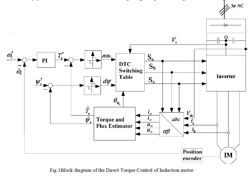
| The block diagram for the conventional DTC scheme of an IM drive is shown in Fig. 1.The basic concept of the Direct Torque Control (DTC) method was proposed by Takahashi and Noguchi in 1986. This method is more used in controlling the induction motor because it is considered a simple and robust method. The power inverter operational control is an important key in this method and modern power electronics has made this cost effective as well. The simple objective is to control two quantities which are the stator flux vector and the electromagnetic torque. Those quantities are directly controlled by selecting the proper inverter state with a combination of sense, command and control feedback loops and by power electronics drive control in the inverter stage. This method and modern power electronics has made this cost effective as well |
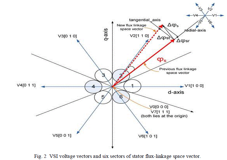
| Based on the three inputs (output digit of torque hysteresis controller, output digit of flux linkage hysteresis controller, and sector number where stator flux-linkage space vector is positioned), the DTC switching table produces the logic signals Sa, Sb, and Sc. These logic signals are used to trigger the switches of the three-phase voltage source inverter (VSI). The possible six active combinations of these logic signals and the corresponding active input voltage vectors of the inverter (V1 to V6) are shown in Fig. 2. |
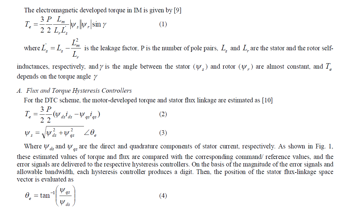 |
| Using this angle, the flux sector number (1 to 6) is determined by using the flux sector algorithm [9]. Therefore, two digits produced by hysteresis controllers and one by flux position are collectively used to trigger the switches of the VSI which selects the appropriate voltage vector by using the classical DTC lookup table [11]. Fig. 2 shows the possible voltage vectors which are employed in the DTC scheme. The appropriate voltage vector in each sampling period is selected in such a way that the torque and flux remain within their respective band limits. |
 |
 |
 |
| B. Torque Ripple Analysis |
| Since none of the inverter switching vectors is able to generate the exact stator voltage required to produce the desired changes in torque and flux, the motor torque keeps on increasing or decreasing until it touches the boundary defined by torque hysteresis bands. The torque ripple is only affected by the width of the torque hysteresis band and is almost independent of the width of the flux hysteresis band [12]. |
 |
 |
 |
 |
| According to the principle of operation of DTC, the torque presents a pulsation that is directly related to the amplitude of its hysteresis band. The torque pulsation is required to be as small as possible because it causes vibration and acoustic noise. However, due to the discrete nature of the control system, there might be still torque ripples even with the zero bandwidth of the hysteresis controller. A small flux hysteresis bands should be preferred when high switching speed semi- conductor devices are utilized because their switching losses are usually negligible with respect on state losses. In this way the output current harmonic can be strongly reduced. The hysteresis band has to be set large enough to limit the inverter switching frequency below a certain level that is usually determined by thermal restriction of power devices. Consequently, the bandwidth of the torque hysteresis controller must be optimized in such as a way that the torque ripple level and switching frequency of the inverter are within acceptable limits. A too small band may result in the selection of reverse voltage vector instead of zero vector to reduce the torque. The selection of reverse voltage vector may then cause torque undershoot. Hence, the torque ripple will become higher than those specified by the hysteresis controller band limits. |
 |
PERFORMANCE ENHANCEMENT OF DTC |
| To enhance the dynamic performance and steady-state accuracy, as well as robustness to external disturbance and motor parameters variations, FLC is used in both outer speed loop and torque hysteresis controller. FLC can handle complicated nonlinear systems, which have a degree of uncertainty. It does not require exact system modeling and parameters; this makes FLC very suitable for motor drive control [13], [14]. |
| A. Fuzzy Logic Speed Control |
| The direct torque control technique can be used even for controlling the motor torque or for speed control of 3-phase induction motors by adding an external speed control loop to the main core of the direct torque controller as shown in Fig.1. In the traditional speed controllers, the actual speed is compared with the reference one. Then the resulting speed error is controlled by a PI controller in order to get fast speed response and to reduce the steady state error to zero. The output of the PI controller is used as a torque reference for the hysteresis torque comparator. PI controller is more suitable in steady state condition and for linear system. But since DTC along with IM is mostly nonlinear, fuzzy controller will be more suitable. Here the fuzzy logic controller is used to control the speed of DTC-based adjustable speed induction motor instead of the conventional PI controllers to overcome its drawbacks. |
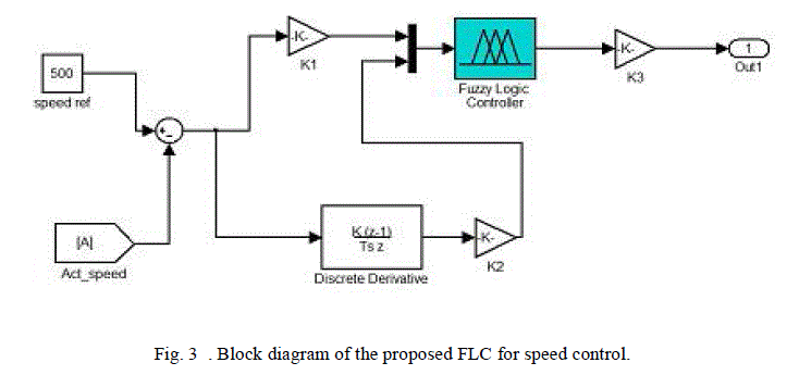
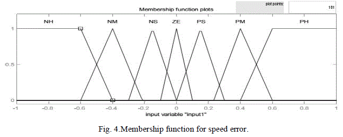
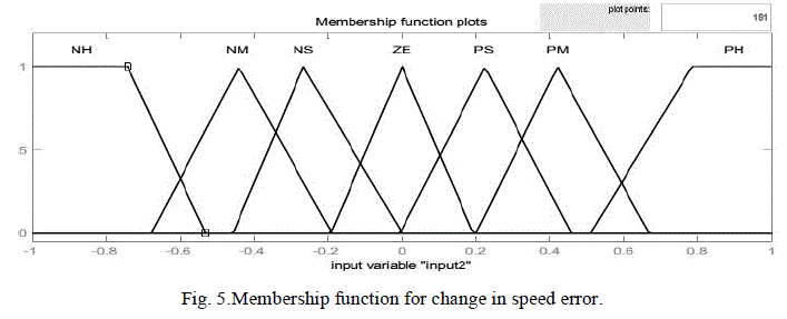
| A diagram for the FLC used for speed control is illustrated in Fig. 3. The inputs are the error between commanding value and real value(E), and its derivative(ΔE). The output is the control increment, whose integral is the real output. The input and output variables are scaled to the range of (-1, 1). This system called PD-type fuzzy logic control, the speed error is the proportional part and the change of speed error is the derivative part. The derivative part is used to predict the speed error and to improve the closed loop stability. The two input signals are multiplied by two scaling factors (K1 , K2) to make the input signals compatible with E and ΔE range. |
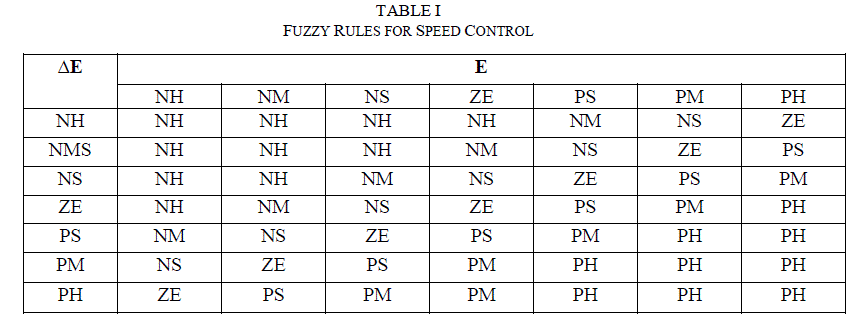
| Figs. 4, 5 and 6 show the membership functions of the inputs and the output, respectively. To obtain a fast response for dynamic performance, and high accuracy for steady state, the asymmetric triangle is selected as the membership function, which is different from the conventional design. Table I shows the inference rule used in this paper, which is the key part of the FLC. By careful design of the inference rule, excellent performance can be achieved. |
| B. FLC for Torque Ripple Minimization |
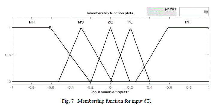
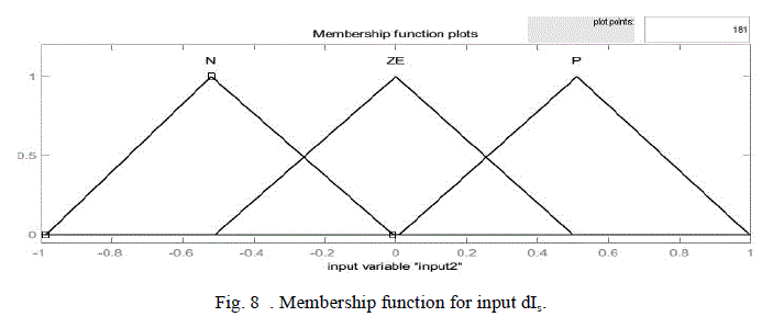
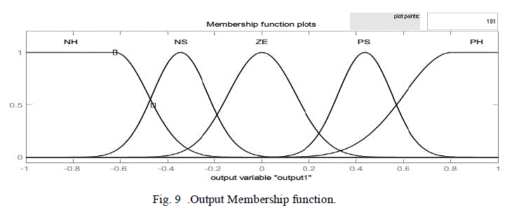
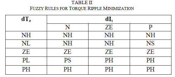
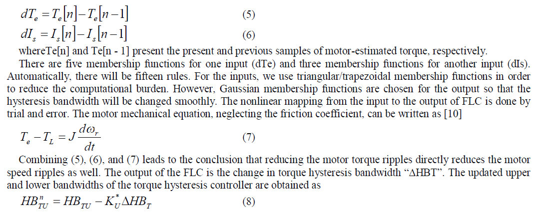
| Fuzzy logic control (FLC) is a control algorithm based on a linguistic control strategy which tries to account the human’s knowledge about how to control a system without requiring a mathematical model. Here, a Mamdani-type FLC is developed to adapt the torque hysteresis band in order to reduce the ripples in the motor-developed torque [15]-[17]. In conventional DTC technique, the amplitude of the torque hysteresis band is fixed. However, in this proposed scheme, the FLC controls the upper and lower limits of the torque hysteresis band on the basis of its feedback inputs. The FLC is used as nonlinear function approximations [16] producing a suitable change in the bandwidth of the torque hysteresis controller in order to keep the torque ripples minimum.Inputs for Fuzzy Logic controller are the motor-estimated torque (2) variation (dTe) and stator current variation (dIs), over a sampling period are chosen as inputs to the FLC which can be defined by the following equations: |
 |
 |
| where HBTU and HBTL are the fixed upper and lower bandwidths of the torque hysteresis comparator. KU, KLare the scaling factors. The fuzzy rules employed are shown in table II |
SIMULATION RESULTS |
| The performance of the FLC-based DTC scheme for IM drive has been investigated extensively at different operating conditions. Sample simulations results are presented below. The nominal IM parameters, used for simulation are given in the Appendix. |
 |
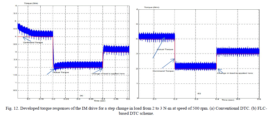 |
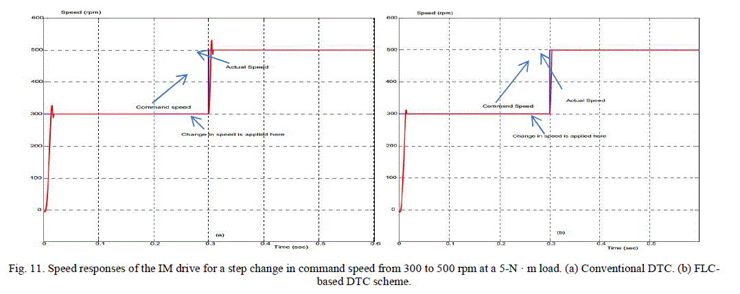
| Figs. 11, 12 show the various IM drive responses for step change in motor load and speed. The change in load is applied at a time of 0.4 s. Fig. 11 shows the simulated speed response using the conventional and the FLDTC schemes. The speed response clearly shows that both the speed overshoot and speed ripples have been reduced considerably by the use of the proposed scheme. The average speed ripples with the conventional DTC scheme are approximately 0.23 and 0.05 rpm, respectively. The use of the FLDTC scheme has reduced these values to 0.1 and 0.09 rpm, respectively. Fig. 12 shows the corresponding torque responses for the conventional and the proposed DTC schemes for a step change in load at 0.4 s. The torque ripple has significantly been reduced in the proposed scheme both in the transient and steady states. |
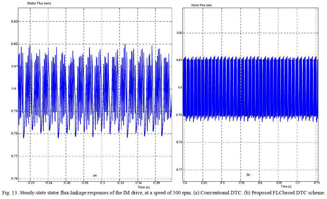
| Fig. 13 shows the flux responses of the drives while the motor is running at 500 rpm. It is found that the proposed variable band torque hysteresis controller-based DTC scheme exhibits smooth response and lesser ripple in flux as compared to the conventional DTC scheme. |
 |
CONCLUSION |
| A novel FLC-based DTC scheme for IM drive has been presented in this paper. Fuzzy logic controllers were designed for improvement of the DTC performance. A fuzzy logic controller has been constructed for speed control while another fuzzy controller is used to adapt the bandwidth of the torque hysteresis controller. A performance comparison of the FLC-based DTC scheme with a conventional DTC scheme has also been provided using simulation. Comparative results show that the torque ripple of the proposed drive has considerably been reduced. The dynamic speed response of the proposed FLC-based DTC scheme has also been found better as compared to the conventional DTC scheme. |
References |
|
|
|
 |