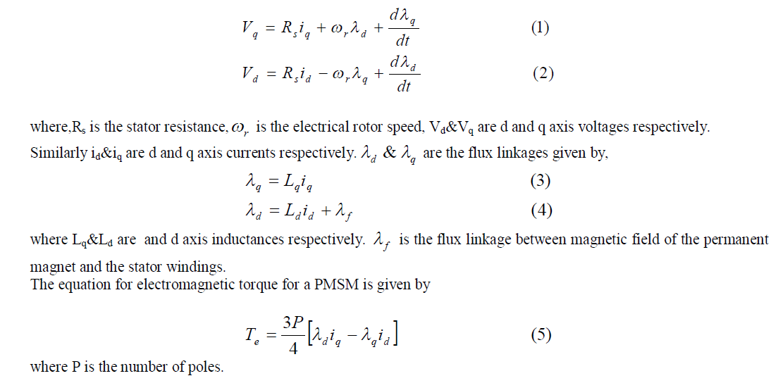
This paper addresses the performance of a permanent magnet synchronous motor (PMSM) speed control system which is driven by a multilevel inverter. A three level inverter is used as the power source for the system which will reduce the winding stresses due to harmonics during the motor operation. A new sliding mode observer based on sigmoid function as switching function is used for estimating the speed and position of PMSM which has the capability to reduce the chattering phenomenon and to make the system more insensitive to disturbances. A fractional order PI controller is used as the speed controller for the system in addition to the two PI controllers that are used as the inner current controllers. Simulation and experimental results can be a testament for the effectiveness of the proposed technique.
Keywords |
| PMSM, Three Level Inverter, Sliding Mode Observer (SMO), Sigmoid function, Fractional Order PI
controller. |
INTRODUCTION |
| PMSMs are a special type of synchronous motors that are being required in various applications. These motors are
available in wide power ranges, ranging from 0.37kW to around 30kW. And it can give an efficiency of about 81-88%
[1]. |
| Field Oriented Control employed in the system helps to achieve independent control over flux and torque of the
machine. Based on the closed loop control of speed and current, the simulation model of the surface-mounted PMSM
(SPMSM) vector control system with a three level inverter with its corresponding Space Vector Pulse Width
Modulation (SVPWM) method was proposed. A sliding mode observer was developed for estimation of speed and
position. In this work, the signum function of normal SMO is replaced by a sigmoid function which will give a smooth
variation during the switching rather than a sudden one. In this study a FOPI speed controller is applied to a PMSM
speed control system based on field oriented control. There are not many works dealing with a PMSM field oriented
control driven by a multilevel inverter and that too operating under a sensorless technique based on a new and
improved sliding mode observer. The tuning of such a PI controller will be done after considering all the parameters of
the system such as inverter delays, motor time constants, delay introduce by Sliding Mode Observers and all the other
delays that can prove to be a problem while tuning the controller. |
PMSM MODELLING |
| According to the theory of AC motors, the mathematical model of the PMSM is developed according to the generalized
theory of machines as follows [2]-[3]: |
 |
THREE LEVEL INVERTER |
| A multilevel inverter is used as the power source for driving PMSM. In comparison to ordinary two level three leg
inverters, the multilevel inverters can give better performance in the aspect of reduction in harmonic stresses on the
winding and hence reduction in heating up of the winding [4]. Also the switches that are required can be of small dv/dt
ratings as the switches are subjected to relatively small changes in voltages. By providing intelligent power modules the
reliability of the power converter can be improved. It will give better electrical performance. However, as the number
of switches is increased the complexity of the system will also increase but it will get justified if its performance and
advantages are considered. The switching strategy based on SVPWM is employed for driving this inverter. |
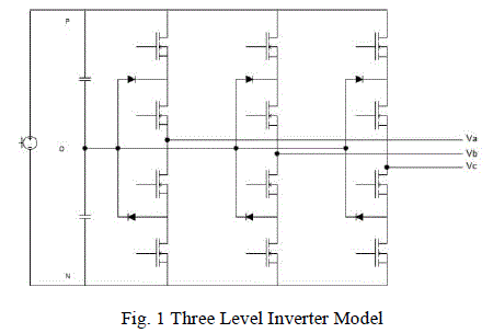 |
| A neutral point clamped three level inverter [4] is used in this work which is shown in Fig.No.1. MOSFET switches
with antiparallel diodes are used. Two almost identical capacitors are required for dividing the voltage evenly. As
compared to two level inverters, three level inverters have smaller output voltage steps that mitigate motor issues due to
long power cables between the inverter and the motor. These issues include surge voltages and rate of voltage rise at
the motor terminals and motor shaft bearing currents. In addition, the cleaner output waveform provides an effective
switching frequency twice that of the actual switching frequency [4]. If an output filter is required, the components will
be smaller and less costly than for an equivalent two level inverter. But the switching strategy for such a converter will
be a little bit complex. So a 3 level space vector pulse width modulation technique is employed for developing the
control signals for the switches. |
SLIDING MODE OBSERVER |
| The sliding mode observer has its base on the variable structure theory [5]. In order to design a sliding mode observer,
first a sliding surface has to be defined. The sliding surface selected for the present work is shown as, |
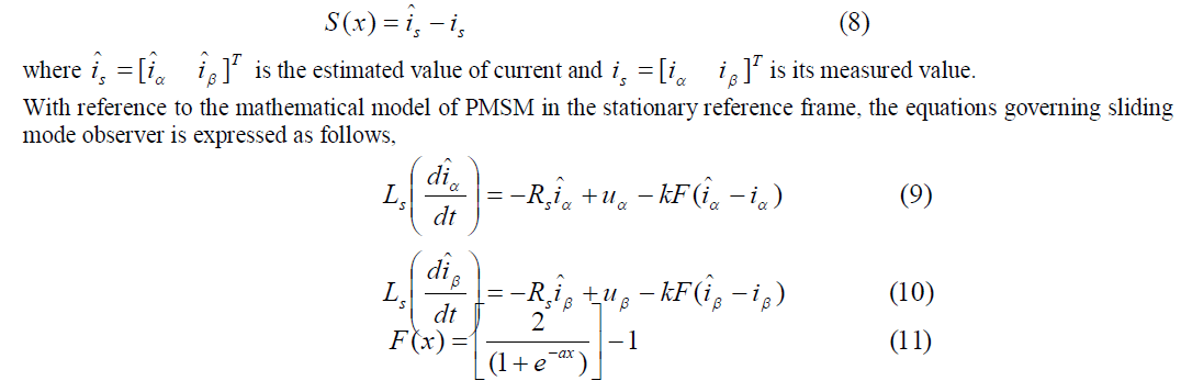 |
| where ‘a’ is an adjustable parameter & k is the observer gain. As sigmoid function is employed here [5], the switching
between 0 and 1 will be smooth so that the effect of chattering will be very less and hence the requirement of a low
pass filter at the output and its phase angle compensation requirement can be avoided. |
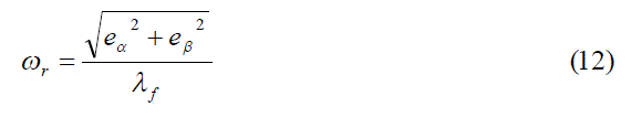
| Speed and position of the rotor can be estimated with the help of this observer. The output of this sliding mode observer
will be back emfs of the machine in the stationary reference frame. This can be employed to estimate the speed and
position as follows, |
 |
FRACTIONAL ORDER PI CONTROLLER |
| The fractional calculus operator is given as follows [6]-[7]: |
 |
| The fractional order PI controller is based on the same principle as that of classical PI controllers, the only difference
being the order of integration will be a non-integer [6]-[8]. The transfer function of a FOPI controller is given by, |
 |
| Where α indicates the order of integration, Kp& Ki are proportional and integral gains. In this work, the order of
integration selected was 0.6. |
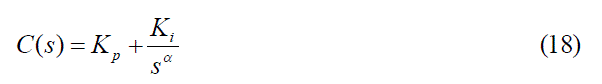
SIMULATION RESULTS |
| The proposed PMSM drive system is compared with an ordinary PMSM vector controlled system (sensored) and the
results are obtained. Simulation model of the proposed system was developed with the help of MATLAB/SIMULINK
interface. All the above mentioned techniques were developed according to the requirement and were interconnected to
obtain the overall system. The proposed drive’s model is shown below, |
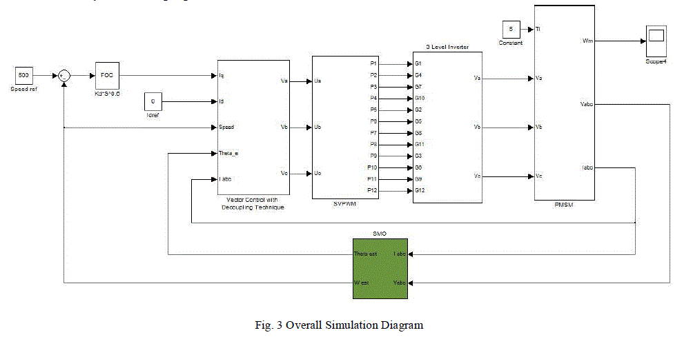 |
| A. Three Level Inverter Performance |
| The performance of the neutral clamped 3 level inverter was obtained as follows: The voltage of A phase is shown
below: |
 |
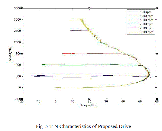
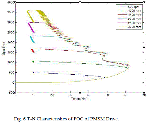
| B. Torque Speed Characteristics |
| In this section, the torque speed characteristics are analysed. For a load torque of 10 Nm, Fig. No: 5 show the torque
speed characteristics of the proposed system and Fig. No: 6 show the same as that of an ordinary vector controlled
system [1]. From the figures 5 & 6, we can say that more smooth response can be obtained with the help of the
proposed drive system. Also the starting torque of the proposed drive system is found to have improved in comparison |
 |
 |
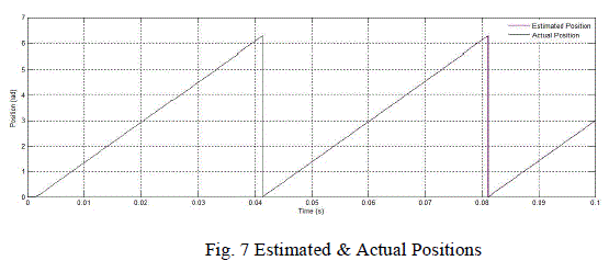
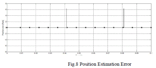
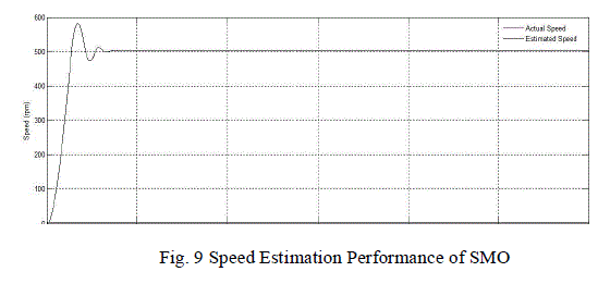
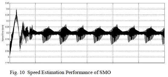
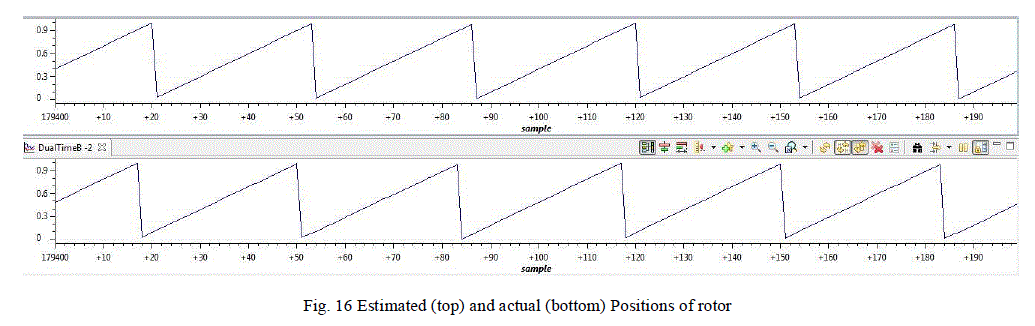
| C. Performance of the Proposed Sliding Mode Observer |
| A new and improved sliding mode observer was used in this technique, which gave the response as shown below. Both
the estimated as well as actual position is shown in the figure. The next figure shows the estimation error. These two
figures gives us the idea that the performance of the new sliding mode observer is satisfactory and can give the speed
and position estimate with least error as possible. The position output wave form has negligible deformation, so we can
say that the effect of chattering phenomenon is very less. The speed estimate is also compared with the actual speed
which substantiates the usage of the improved sliding mode observer. |
 |
 |
 |
 |
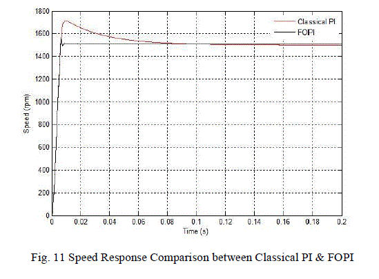
| D. Performance of FOPI Controller in Comparison with Classical PI Controller |
| The performance of FOPI and classical PI controllers are shown in Fig. No: 4. From the figure, it can be seen that for a
reference speed of 1500 RPM, the response of FOPI controller was found to be far superior to the classical PI controller.
The overshoot as well as settling time of the system was improved. |
 |
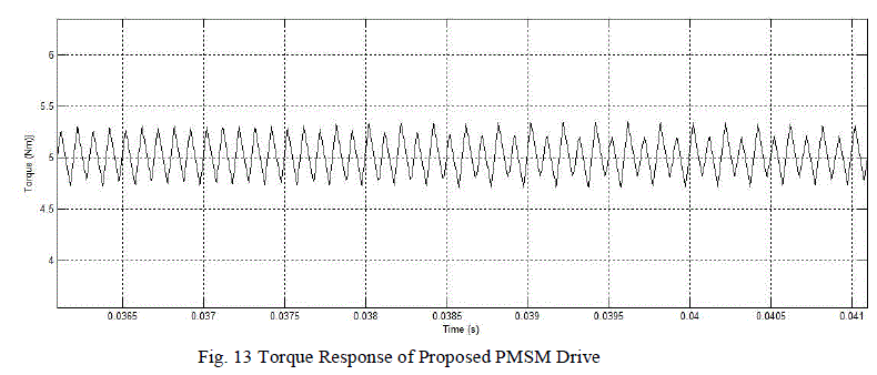
| E. Torque Response |
| The torque responses for the ordinary vector control system for a load torque of 5Nm & the torque response for the
proposed drive system under same conditions are shown below. These graphs indicate that the torque ripple reduction
is significant with the help of the proposed system. The graphs are shown below |
 |
 |
EXPERIMENTAL RESULTS |
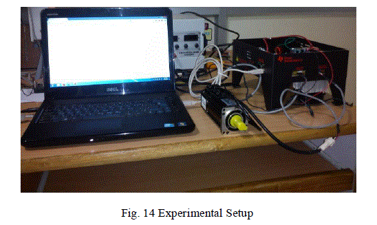
| The experimental setup is as shown below. The experiment was done with TMS320F28035 DSP control card, a two
level inverter, Anaheim made PMSM servo motor. |
 |
 |
 |
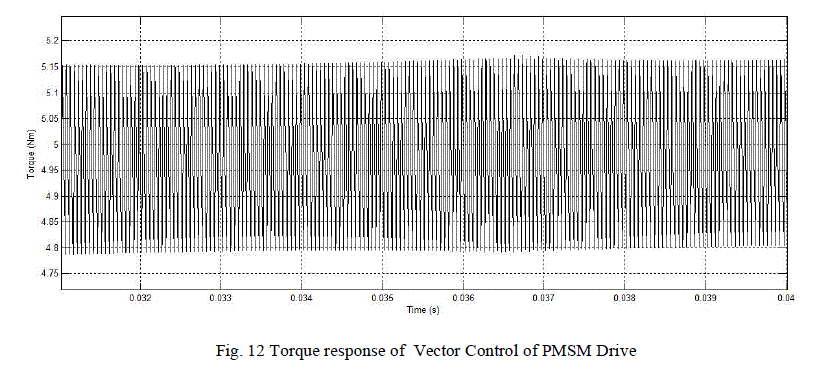
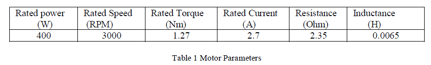
| The experiment was done with the help of DSP. The DSP employed was TMS320F28035 control card. PMSM used is
of Anaheim made. The parameters of the motor are shown in Table 1. The experimental results are shown in Fig. 11
&12. |
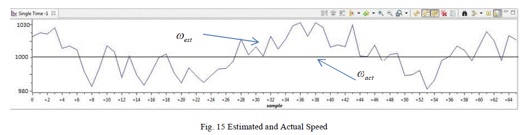
| From the graphs it can be said that the position and speed were estimated correctly and the closed loop operation of the
drive was made possible in the hardware also.The motor was found to operate with less noise and the tracking
performance was also satisfactory. |
 |
CONCLUSION |
| In this paper, a sensored vector control of PMSM was considered andvector control incorporating decoupling control
technique was implemented. A new sensorless technique based on an improved sliding mode technique was introduced
whose working was found to be more than satisfactory in simulation as well as in its hardware counterpart.With the
help of SMO technique, position and speed were sensed with negligible error. Then a neutral point clamped three level
inverter was used instead of a two level inverter which helped to reduce the heating of the winding due to harmonics
and considerably reduced the stresses on the switches used. After these modifications, the torque response was found to
have less torque ripples. Then the classical PI controller was replaced with a fractional order controller, which
improved the performance of the system to a great level as shown in the results. So the proposed technique
incorporating new sliding mode observer, three level inverter and fractional order PI controller into the ordinary vector
control system for a PMSM drive was found to have more advantages than the basic system. Compared with the
ordinary PMSM drives, the proposed technique can be said to have superior characteristics. |
ACKNOWLEDGEMENT |
| I express my sincere gratitude towards Prof. Mary George, Head of the Department of Electrical Engineering, for her
valuable suggestions and support. I am really grateful for her expert opinions on the topic, which I made use while
doing my work.I express my gratitude to P.G Coordinator, Prof.C.K Vijayakumari and my guide Mrs.Radhika.R, for
their co-operation and guidance for preparing and presenting this paper. I would like to thank them for being patient
with me and for helping me to understand the shortcomings in my work.Last but not the least; I acknowledge the grace
and power of Almighty God without whose blessings none of this would have been possible. |
References |
- Amor Khlaief, MoussaBendjedia, Mohamed Boussak, A Nonlinear Observer for High-Performance Sensorless Speed Control of IPMSM Drive, IEEE Transactions On Power electronics, vol 27, no. 6, June 2012
- KiranBoby, Acy M Kottalil, N P Ananthamoorthy, Mathematical Modeling of PMSM Vector Control system based on SVPWM with PI Controller Using MATLAB, International Journal of Advanced Research in Electrical, Electronics and Instrumentation Engineering Vol. 2, Issue 1, January 2013
- P C Krause, Analysis of Electric Machinery and Drive System, Second Edition, Wiley Inter Science
- Subrata K Mondal, Bimal K Bose, ValentinOleschuk and Joao O P Pinto, Space Vector Pulse Width Modulation of Three Level Inverter Extending Operation into Over Modulation Region, IEEE Transactions On Power electronics, vol 18, no. 2, March 2003
- Hongryel Kim, Jubum Son, and Jangmyung Lee, A High-Speed Sliding-Mode Observer for the Sensorless Speed Control of a PMSM, IEEE Transactions On Power electronics, vol 58, no. 9, September 2011
- Li Chun-Lai, Yu Si-Min, Luo Xiao-Shu, Fractional-order permanent magnet synchronousmotor and its adaptive chaotic control, Chin. Phys. B Vol. 21, No. 10 (2012)
- ConcepciÃÆón A. Monje Ãâ÷ YangQuan Chen Blas M. Vinagre Ãâ÷ DingyÃÆüXue Ãâ÷ Vicente Feliu, Fractional-order Systems and Controls: Fundamentals and Applications, SpringerManuel A. Duarte-Mermoud, Felipe J. Mira, Ian S. Pelissier and Juan C., Travieso-Torres, Evaluation of a Fractional Order PI Controller Applied to Induction Motor Speed Control, 2010 8th IEEE International Conference on Control and Automation Xiamen, China, June 9-11, 2010.
|