Driverless trains are equipped with a control system, which is programmed to make them following a specific path. Stations on such a path, timings of the train and distances between stations are all predefined. Messages and warnings are automatically generated and announced to the passengers. This paper presents the development process of a prototype for a driverless train implemented using a PIC microcontroller. Simulation for the system's circuits is done with the aid of Proteus software. The hardware circuits, which are built on printed circuit boards (PCB) are interfaced with actuators and sensors for automation purposes. The hardware is assembled in a toy-like prototype train. The C programming language is used for programming the microcontroller.
Keywords |
| Driverless train; Automatic train operation; Full automation; Unmanned train operation. |
INTRODUCTION |
| Modern technologies are being integrated in almost all aspects of our life including transportation, where a lot of
advancement has been made. Railroad transport, for instance, has undergone a huge transformation, starting with the
early steam operated engines to the most recent bullet train. |
| Many developments in railroad transport has utilized the existing infrastructure, where the existing metro system is
being modernized and equipped with automatic train control and safety system in order to make them more efficient.
Driverless automated concepts have been adopted, and the first recorded implementation was the London underground
Victoria line, opened in 1967 [1]. Many other rail lines are then automated with the aim of reducing operational costs
and improving the frequency of service. In automated train control (ATC) systems, different grades of automation
(GoA) have been incorporated. The grades of automation (GoA2, GoA3, GoA4) are corresponding to Semi-automated
Train Operation (STO), Driverless Train Operation (DTO), and Unmanned Train Operation (UTO) respectively [2].
Grades of automation (GoA) are defined according to which basic functions of train operation are responsibility of
staff, and which are the responsibility of the system itself. For example, a Grade of Automation 0 (GoA 0) would
correspond to on-sight operation, like a bus running on street traffic. GoA 4 would refer to a system in which trains are
run fully automatically without any operating staff onboard. Systems work within the GoA4 are normally having an
overall signalling system with the necessary connections, automatic train supervision, track vacancy detection and
communication functions [3]. In fact any new metro system constructed and implemented today integrates at least some
level of automation reaching out to new fully driverless technologies. |
| The Unmanned Train Operation (UTO), which is featured by the highest degree of automation is not a very recent
development with the first UTO lines date from 1981 [3,4]. However a fully driverless system was only implemented
in 2003 in Singapore, while the 75 Km Dubai line is the longest metro line in the world [5]. |
| There has been a continuous research intended to enhance the overall automation system functions and performance of
the trains. In [6], Han et al present the development of Korean standards of an on board train automatic control and show results of running test on a Korean train line. Jun et al in [7], suggest a development strategy of a multi-train
operation simulator to support R&D works for future railway system, where a computer-based simulation models of
train, station, rail and railway operation system as an agent is designed. Regarding the Communications-Based Train
Control (CBTC), Georgescu [8], proposes a systematic approach that may be used to determine the most efficient way
to fulfil the requirements specific to each customer faced with driverless operation. Georgescu’s paper also defines
required functionality to obtain the desired performance and cost, as well as issues related to the operability,
maintainability, and availability of different types of driverless CBTC systems implementations. In the paper of H. Yun
and K. Lee [9], a data transmission technology that is capable of calculating the required frequency bandwidth, having
the transmission capacity of the communication-based train control system, and that also uses the wireless mesh
network, is proposed. |
DRIVERLESS TRAIN IMPLEMNTATIONS |
| The duty of any train transportation system is to provide secure, consistent, efficient and high-quality service to
passengers. As many rail lines run at or near their capacity limits, automation is often the only way to maximize the
operational performance of a train service system. Implemented on existing lines, automation is in many cases more
cost-effective than constructing new lines or extending platforms. Fully automated metros in cities like Kuala Lumpur,
Dubai, Tokyo and Copenhagen, have been running for several years. Other major cities across Europe, North America
and Asia are following the example and have partly automated their systems. |
| The move to train automation can be justified by their numerous benefits: Schedules of train operations become more
exact and timely, the frequency of the trains can be improved, especially in low traffic hours, as more and shorter trains
can be inserted in traffic without the need for more operational staff, and the enhanced safety, where the element of
human error is taken out completely. Besides, automation can reduce the wear-and-tear of train by optimizing energy
consumption and potentially reduce operating costs through more effective and regular train operation.
In a fully automatic driving system, care should be taken for all the processes that are normally requiring human
intervention. The initial train departure, trips between two stations, timing of train stoppage at individual stations, and
controlling the train doors are examples of such processes. In addition, there are normally more activities that should be
automated too. The safety systems represents important activities that driverless trains must have; like fire alarms with
automatic fire fighting systems, sensing of any possible damage in the track and providing the information to the next
train on the same track as well as to the base [10]. |
| In this project, part of this automation tasks are considered, and a microcontroller-based prototype is developed.
Actions such as; traveling through a given path with predefined stations, sensing the arrival at the station and hence,
proper stopping are implemented in the prototype. Messages that are synchronized with the train's progression through
its path are announced to passengers via a display. Moreover, there are alarm signals produced as appropriate.
Controlling of the doors in terms of open and close and timings of such actions are considered. |
DRIVELESS TRAIN PROTOTYPE: DESIGN AND SIMULATION |
| The development activities of the driverless train prototype can be broadly grouped into simulation and hardware
implementation. The Proteus software is used in system simulation, with the basic elements involved in the automation
represented in the block diagram shown in fig 1. |
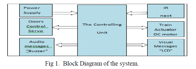 |
| The blocks shown in the above figure are put together as a design to form the automated functions of the driverless
train, and the ISIS schematic capture of the Proteus software is used to edit this design. Actions of automation are
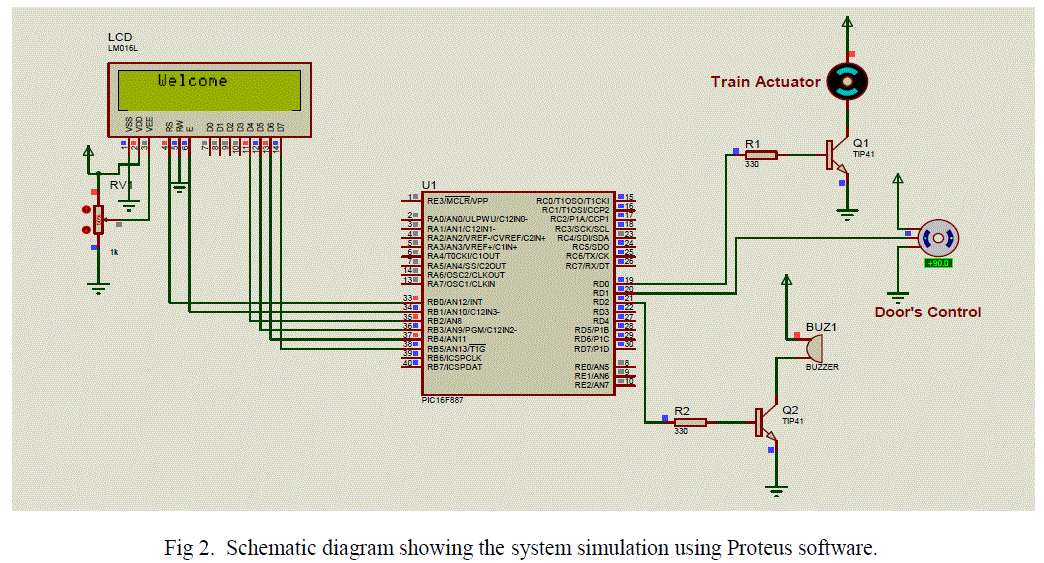
performed by developing a program using microC [11], a language that is used for programming microcontrollers. Fig.
2 is showing the schematic diagram of the circuit that is used for simulation. In this figure, it's apparent that PIC16F887
is used as the main controlling unit. This microcontroller is chosen because of its availability in the market, and the
well known popularity of the PIC series of microcontrollers. Another fact is that PIC16F887 is having both analog and
digital ports, and this feature is actually suiting our system that has both analog and digital inputs and outputs.
After having the program loaded to the microcontroller, the behavior of the system is observed throughout the
simulation process and adjustments are made to the design and operation activities. On the simulated LCD appearing in
fig 2, a welcoming message is displayed, where the train is still stopping at the first station with its doors open for
passengers to enter. At this situation, the actuator simulating the motion of the train is OFF, and the doors’ control
actuator is at OPEN state. |
 |
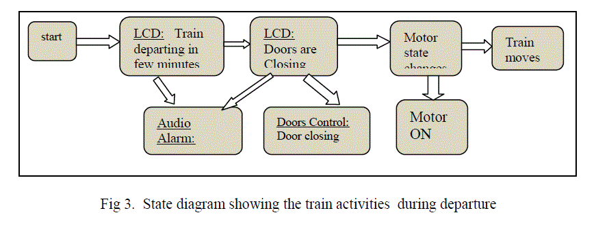
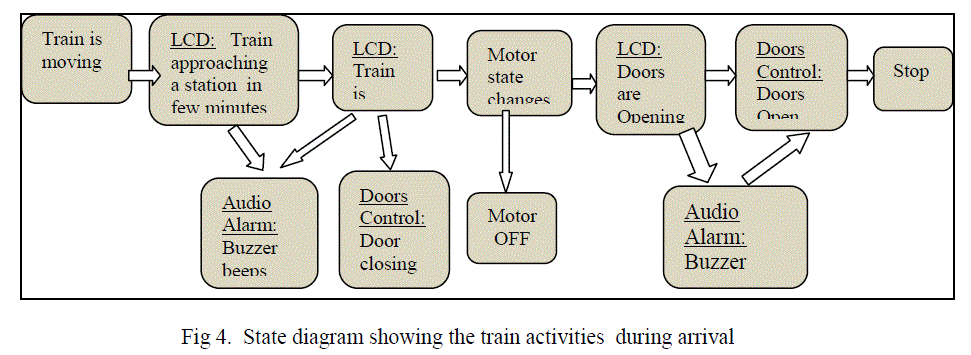
| Further train activities, while its departing a station and/or arriving at a station are considered in the simulation. Such
activates, and their flow are shown in the state diagrams of fig. 3 and fig. 4. |
 |
 |
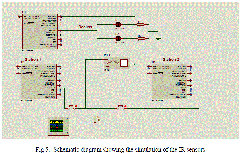
| For the train to automatically and reliably stops at stations, different techniques may be applied. Distances between
stations, for instance, may be used to manage such actions by providing them as information to the control unit. In our
system, we have used IR sensors, where at appropriate locations with respect to each station, an IR transmitter is
positioned. Whereas the other part of the IR sensor, the receiver, is installed on the train. Whenever a train travelling
between stations, decodes a relevant IR signal, it will start its preparation to stop at the coming station. The Proteus
simulation of the IR circuits are shown in fig. 5. In this figure, it can be noticed that three pieces of a smaller
microcontroller chips are used (PIC16F628). This type of PIC16 series has only 18 pins and two ports, which are
found enough for the task of IR transmission and reception circuits. |
 |
THE HARDWARE IMPLEMNTATION |
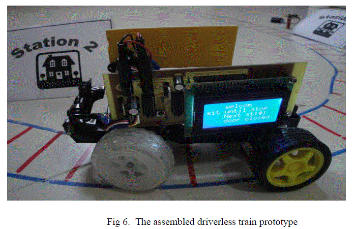
| After testing the circuits with simulation, hardware implementation started by assembling the components
on printed circuit boards (PCB). ARES software, which is part of Proteus is used to produce the schematic
for three PCBs that are used in implementing the hardware system. One PCB is designed to hold the main controller circuit components, and two small identical PCBs are used to implement the IR sensors. A PIC
microcontroller unit is used in each of the three circuits. The main controller circuit is installed in a toytrain
representing the prototype and interfaced with a dc motor to actuate the train movement, another
actuator to control the opening and closing of the door, an LCD to display messages, and a buzzer to
announce audio warnings. An IR detector is also incorporated in the main control circuit, while the two IR
transmitters are located along the path of the train to present stations at which the train has to stop. The
assembled hardware system is illustrated in fig. 6. |
 |
RESULTS AND DISCUSSION |
| An example of how embedded technology is used in application, specifically in the transport sector is presented in this
paper. A driverless train prototype has been developed as a microcontroller-based system. Both software and hardware
parts are included in the development process. The programs which are written using micro C language were
simulated together with other system components using the Proteus software. In the hardware part, all the circuitry
required to interface with the PIC microcontroller are designed and built. The development of the prototype has passed
through stages which ended up with a working system representing many features of automation. The prototype train
is following a prescheduled path in terms of proper stations’ starts and stops, announcing messages to passengers, and
issuing alerts. |
| Despite the incorporation of all the presented features, a room still there for more improvements to be added.
Currently, the train is driving forward following a circular path. The path, however can be reprogrammed in such a
way that the train, for the same path follows forward and reverse journeys. Another improvement can be added such
that more than a single path for the train to follow is offered to choose from. Alternative paths may have different
stations to stop at, and consequently different timings. |
CONCLUSION |
| The driverless train prototype that is presented in this paper is in fact a final year project. A general conclusion that
can be said about such engineering projects is that they are introducing students to an open horizon of developments.
Such projects can only represent a minor part of what the future and technology integration may look like for the
modernization of different service sectors including transport. Researching and developing a working prototype
enhance self confidence and assure that it is possible to design a system and apply it for solving a particular problem
by acquiring the necessary information. Moreover, developing a prototype system can serve as a basis of a far more
sophisticated and advance form of control system such as a real driverless train system. |
References |
- B.W.C. Cooke. "Proposed New London Underground".The Railway Magazine (London) 101 (648): 279âÃâ¬Ãâ281. April 1955.
- E. Fischer. "Justifying automation". Railway-Technology.com. 23 August 2011.
- S. Cappaert-Blondelle. Metro Automation Facts, Figues and Trends.The International Association of Public Transport (UITP). Technical report . Belgium. 2012.
- J.M. Erbina, and C. Soulasa. Twenty Years of Experiences with Driverless Metros in France. VWT 19 proceedings. Dresden. 2003.
- Transportation system division. The Dubai Metro, the WorldâÃâ¬Ãâ¢s Longest Fully Automated Metro Network. Mitsubishi Heavy Industries Technical Review Vol. 49.No. 2 .June 2012.
- S. HAN, S. LEE, W.KIM. Development of Onboard Train Automatic Control System for Korean Standard EMU. Processing's of the ISIE 2001 conference. 2001. Pusan, KOREA.
- H. Jun, and S. Choi. Development of a Multi-train Operation Simulator with Interactive Human Computer Interfaces. International Conference on Hybrid Information Technology (ICHIT'06). 2006. Cheju Island, Korea.
- M. P. Georgescu. Driverless CBTC âÃâ¬Ãâ specific requirements for CBTC systems to overcome operation challenges. WIT Transactions on The Built Environment, Vol 88. 2008. pp. 401-409.
- H. Yun, and K. Lee. Development of the Train Control System Data Transmission Technology Using a Wi-Fi Mesh. Proceeding if the ICTC 2011.Seoul . Sept 2011. Pp 406-410.
- M. Siemiatycki. Message in a Metro: Building Urban Rail Infrastructure and Image in Delhi, India. International Journal of Urban and Regional Research, vol. 30, pp. 289-92.
- M. Verle .PIC Microcontrollers - Programming in C. mikroElektronika; 1st edition .2009.
|