International Journal of Advanced Research in Electrical, Electronics and Instrumentation Engineering
ISSN ONLINE(2278-8875) PRINT (2320-3765)
ISSN ONLINE(2278-8875) PRINT (2320-3765)
| Jigar S.Sarda, Vibha N.Parmar, Dhaval G.Patel and Lalit K.Patel Department of Electrical Engineering, C.S.P.I.T, Charusat University, Gujarat, India. |
| Related article at Pubmed, Scholar Google |
Visit for more related articles at International Journal of Advanced Research in Electrical, Electronics and Instrumentation Engineering
This paper presents a novel method for optimal location of FACTS devices in a multi machine power system using Genetic Algorithm(GA).Using the proposed method, the location of FACTS controllers, their type and rated values are optimized simultaneously. Among the various FACTS controllers, Static Var Controller (SVC), Thyristor Controlled Series Compensator(TCSC) and Unified Power Flow Controller(UPFC) are considered. The proposed algorithm is an effective method for finding the optimal choice and location of FACTS controllers and also increasing loadability of the line and minimize losses using GA and conventional fast-decoupled 's power flow method. A MATLAB coding is developed for the simulation. Different loading conditions of the power system are considered. The proposed algorithm has been applied to IEEE-30 bus system.
Keywords |
| FACTS Devices; Genetic Algorithm; Optimal location, Loadability. |
INTRODUCTION |
| Since the 1970’s, energy cost, environmental restrictions, right -of -way difficulties along with other legislative social and cost problems have postponed the construction of both new generation and transmission systems in India as well as most of other countries. Recently because of adoption of power reforms or restricting or deregulation, competitive electric energy markets are being developed by mandating into a separation of generation and transmission is taking progressively; at last, every consumer will be able to buy his own electricity from any desired source. The Western Europe countries like Chile, UK, Norway or the USA have already set off on the way to the liberalization , but in every case the economical effects: i) a price decrease of the KWH particularly for large customers, and ii) a reductions of the disparities in regional costs are same on the technical side. An increase of the unplanned power exchanges due to the competition among utilities and to contracts concluded directly between producers and consumers. If the exchanges were not controlled, some lines on particular paths located may become overloaded called congestion, and full capacity of transmission interconnections could not be utilized. In deregulated environment, this kind of control seems to be not possible any more. Parallel to the deregulation, electrical load carries on increasing. Of course this growth has been practically stabilized in developed nations, but some transmission lines are already close to their thermal limit. Therefore it is attractive for electrical utilities to have a way of permitting a more efficient use of the transmission lines by controlling the power flows. |
| Appearance of FACTS devices (Flexible AC Transmission Systems) opens up new opportunities for controlling power and enhancing the usable capacity of existing transmission lines. For a meshed network, an optimal location of FACTS devices allows to control its power flows and thus to increase the system load ability. However, a limit number of devices, beyond which this load ability cannot be improved, has been observed . In this paper, three different types of devices, with specific characteristics, have been selected and modeled for steady-state analysis. They are used in the power transmitted by the network to be maximum by controlling the power flows. The optimal location of a given number of FACTS is a problem of combinatorial analysis. To solve this type of problem, Genetic Algorithms (GAs) have chosen. |
| This paper is organised as follow: Section I gives the introduction of the work. Section II is helpful to understand the background of FACTS devices. Section III explain mathematical model of FACTS devices. Section IV is helpful to understand proposed algorithm. Section V shows the performance of proposed technique and at last Section VI concludes the paper and followed by references. |
GENERALITIES OF FACTS |
| In a power system, FACTS devices may be used to achieve several goals. In steady-state, for a meshed network, they can permit to operate transmission lines close to their thermal limits and to reduce the loop flows. In this respect, they act by supplying or absorbing reactive power, increasing or reducing voltage and controlling series impedance or phase-angle. Their high-speed command gives them several qualities in dynamic stability. In particular, they are capable to increase synchronizing torque, damp oscillations at various frequencies below the rated frequency (0.2 to 1.5 Hz), support dynamic voltage or control power flows. Moreover, FACTS devices may have benefits in case of short circuits, by limiting short-circuit current. Another advantage of FACTS devices consists in the fact that this technology gives the opportunity to extend the current transmission line limits in a step-by-step manner with incremental investment when required. |
| Different types of devices have been developed and there is various ways to class them: i) the technology of the used semiconductor, ii) the possible benefits of the controllers, and iii) the type of compensation. According to the last classification, can be divided in to four categories of FACTS controllers: |
| • Series controllers |
| • Shunt controllers |
| • Combined Series-Shunt controllers |
| • Combined Series-Shunt controllers |
| Several FACTS devices exist and each one has its own proprieties and may be used in specific contexts. |
Choice of FACTS Devices:- |
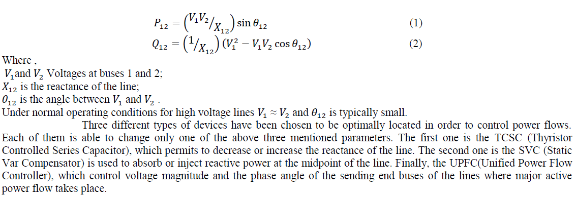
| In an interconnected electrical network, power flows obey Kirchhoff’s laws. Usually, the value of the transverse conductance is close to zero and for most transmission lines, the resistance is small compared to the reactance. By neglecting the transverse capacitance, active and reactive power transmitted by a line between two buses 1 and 2 may be approximated by the following relationships: |
 |
MATHEMATICAL MODEL OF FACTS DEVICES |
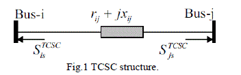
| In this paper steady state model of FACTS devices are developed for power flow studies. So TCSC is modelled simply to just modify the reactance of transmission line. SVC and UPFC are modelled using the power injection models. Models integrated into transmission line for TCSC and UPFC and SVC is modelled and incorporated into the bus as shunt element of transmission line. Mathematical models for FACTS devices are implemented by MATLAB programming language. |
| TCSC:- TCSC acts as the capacitive or inductive compensator by modifying reactance of transmission line. This changes line flow due to change in series reactance. In this paper TCSC is modelled by changing transmission line reactance as below: |
 |
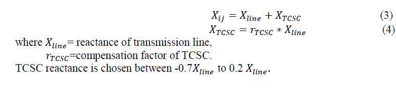 |
| SVC:- SVC can be used for both inductive and capacitive compensation. |
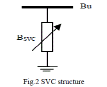 |
| In this paper SVC is modelled as an ideal reactive power injection at bus i: |
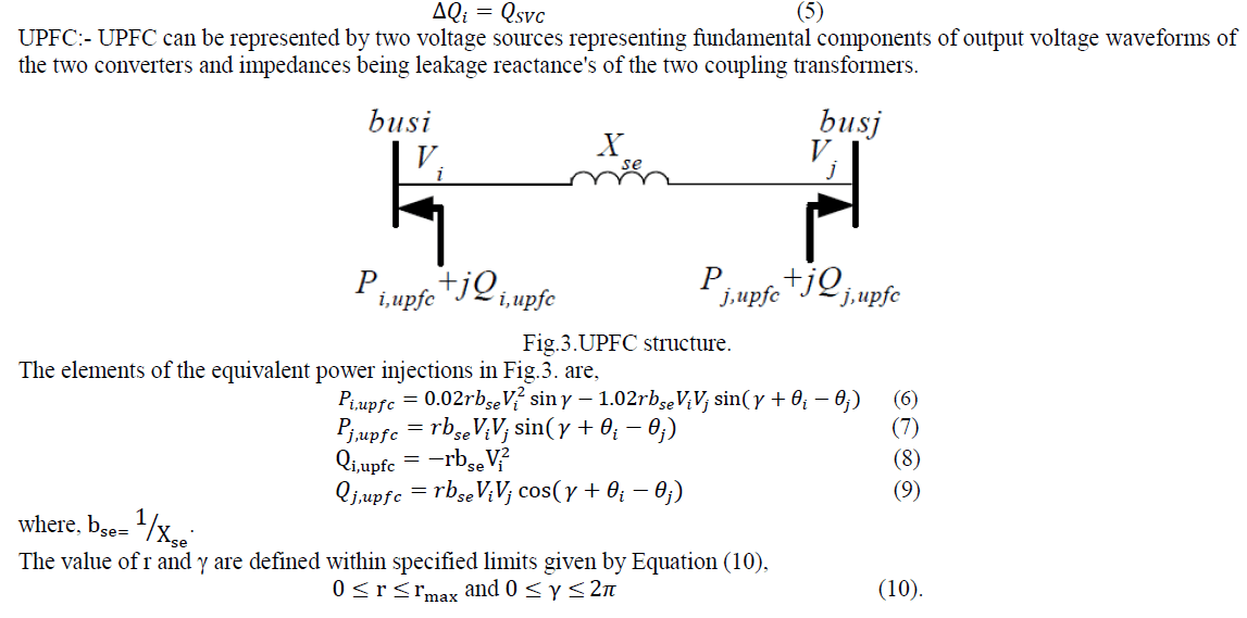 |
OPTIMIZATION ALGORITHMS |
A. Description of the Used Genetic Algorithm. |
| The goal of the optimization is to find the best location of a given number of FACTS devices in accordance with a defined criterion. A configuration of FACTS devices is defined with three parameters: the location of the devices, their types and their values. In order to take into account the three aforementioned parameters in the optimization, a particular coding is developed. An individual is represented with three strings of length , where is the number of devices to locate optimally. The first string corresponds to the individual represents the values of the devices. It can take discrete values contained between 0 and 1; 0 corresponding to the minimum value that the device can take and 1 to the maximum. According to the model of the FACTS, the real value of the device is calculated with the relation. |
 |
| The creation of an individual is done in three stages. First, setting values of the devices are randomly drawn among the possible. The second string, referred to the types of the devices, is obtained by randomly drawing numbers among the selected devices. Finally a set of branches of the network are randomly drawn and is put in the first string. As previously mentioned, the order of the branches is not important and different individuals may represent the same configuration of FACTS devices. Thus, if we decide to optimally locate only one type of device, this string will contain the same character. To obtain the entire initial population, these operations are repeated times. Then, the objective function is computed for every individuals of the population. It represents a mathematical translation of the optimization to realize and does not have to be continuous or derivable. It has to be elaborated so as to favour the reproduction of good individuals without preventing reproduction of interesting others. In our case, the objective function is defined in order to quantify the impact of the FACTS devices on the state of the power system. The move to a new generation is done from the results obtained for the old generation. A biased roulette wheel is created from the obtained values of the objective function of the current population. After that, the operators of reproduction, crossover and mutation are applied successively to generate the off springs. The crossover may occur with a probability pc; generally close to 1. A double crossover is applied. Two crossing sites are picked up uniformly at random along the individuals. Elements outside these two points are kept to be part of the off springs. Then, from the first position of crossover to the second one, elements of the three strings of both parents are exchanged. As previously mentioned, only one FACTS device per branch is authorized. Therefore, if the crossover leads to place a second device on a branch, a correction has to be applied. In the case where an element of the first string already occupies a position in the kept part of the parent, it is replaced by the element corresponding to the same position in the other parent. This algorithm is repeated until an element not already present in the string is reached. Mutations are possible independently on all elements of the three strings of an individual. A specific probability is applied for each string: for the first string, for the second and for the last. These probabilities change with the generations. When a mutation occurs on the first string, the one related to the location, a new line among the set of branches having no FACTS is randomly drawn. In the case of mutation on the two other strings, a new value is drawn among the set of possible ones. Operations of selection, crossover and mutation are repeated until the number of desired offsprings is created. The objective function is then calculated for every offsprings and the best individuals among the entire pool, comprising parents and their offsprings, are kept to constitute the new generation. By this way, the objective function of the best individual of the new generation will be the same or higher than the objective function of the best individual of the previous generation. Similarly, the average fitness of the population will be the same or higher than the average fitness of the previous generation. Thus the fitness of the entire population and the fitness of the best individual are increasing for each generation. |
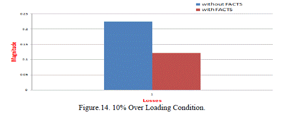
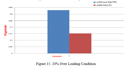
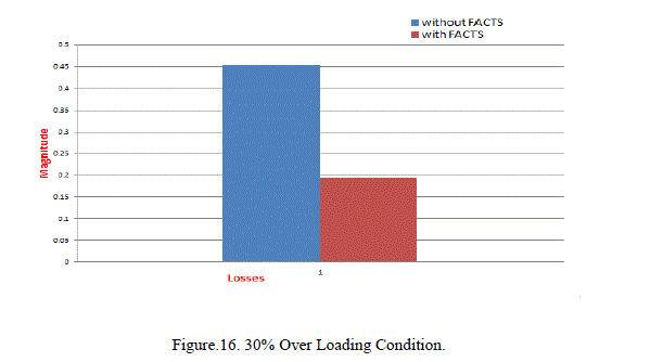
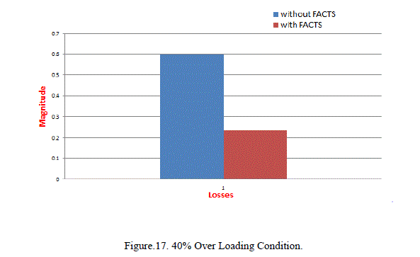
CASE STUDY & RESULTS |
A. Objectives of the Optimization. |
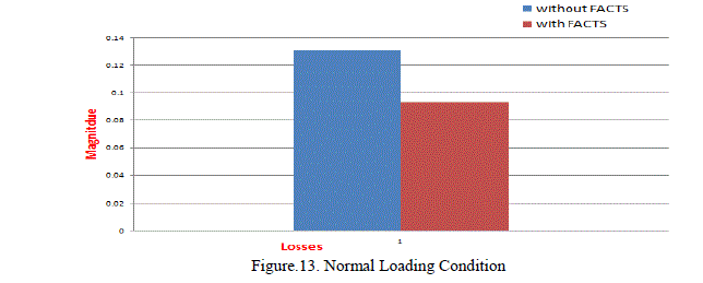
| The goal of the optimization is to perform a best utilization of the existing transmission lines. In this respect, the FACTS devices are located in order to maximize the system loadability while observing thermal and voltage constraints. In other words, we look for increasing as much as possible the power transmitted by the network to the consumers, keeping the power system in a secure state in terms of branch loading and voltage levels. The objective function is built in order to penalize the configurations of FACTS leading to overloaded transmission lines and over- or under-voltages at buses. Only the technical benefits of the FACTS controllers, in terms of loadability, are taken into account. Other criteria such as costs of installing and maintaining devices are not taken into account. The objective function is related to the branch loading and penalizes overloads in the lines. This term, called Ovl, is computed for every line of the network. While the branch loading is less than 100%, its value is equal to 1; then it decreases exponentially with the overload. To accelerate the convergence, the product of all objective function is taken. |
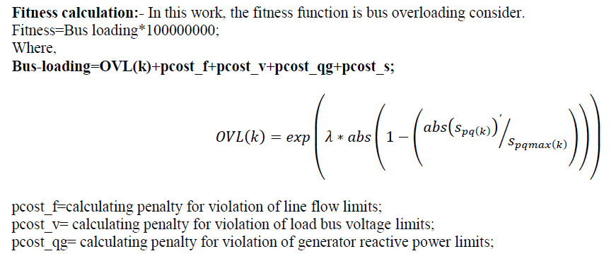 |
| pcost_s= calculating penalty for violation of slack bus active power limits; |
| B. Optimization Strategy:- |
| As explained previously, the aim is to find the maximum amount of power that the power system is able to supply without overloaded line. We look for locating a given number of FACTS devices to increase as much as possible the capacity of the network. For several number of FACTS devices, we seek the best location with the best values of the most appropriate controllers. When the number of devices is increased, the results obtained previously are not taken into account. In others words, FACTS devices may disappear from specific lines to reappear on others when their number is increased. For a given number of devices, the strategy consists of adding to the power supplied as long as a configuration of FACTS permits to keep the power system in a secure state. The stop criterion is either the maximum number of generations or a solution with an objective function equal to 1. In the first case the algorithm is stopped, otherwise the load is raised and a new optimization starts again. All loads are increased in the same proportion and real power of generators as well. Additional losses due to the increasing of the power transmitted are shared out among all the generators proportionally to their power. |
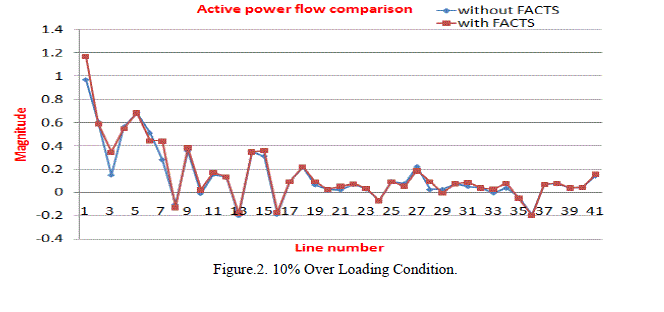
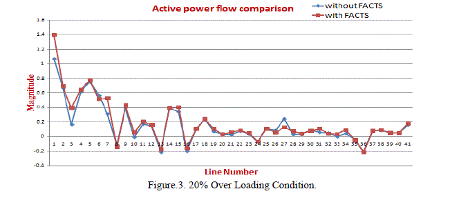
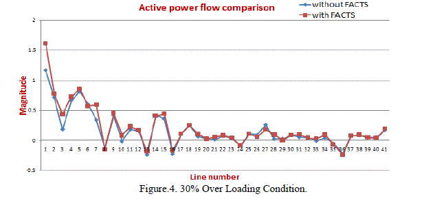
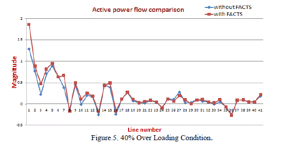
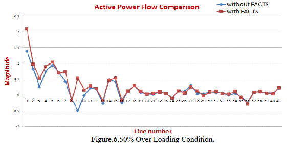
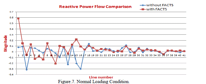
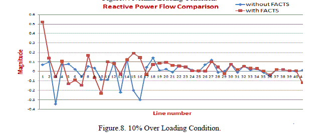
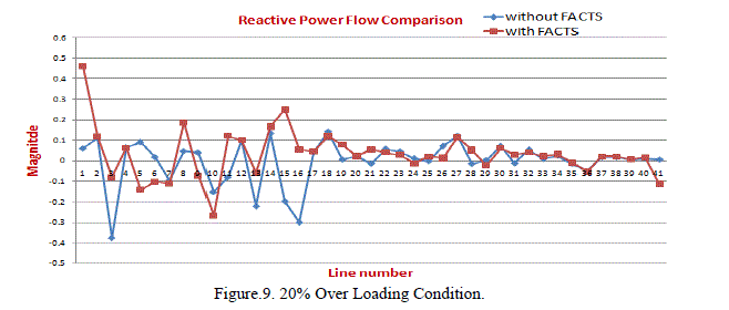
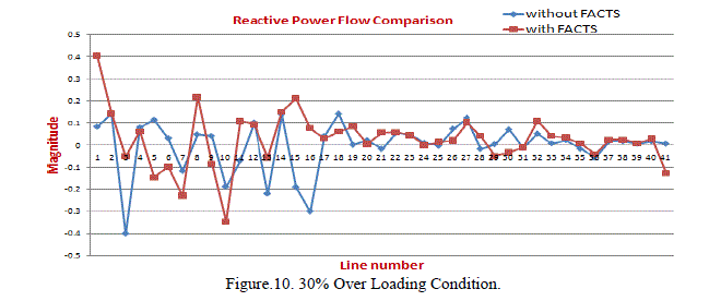
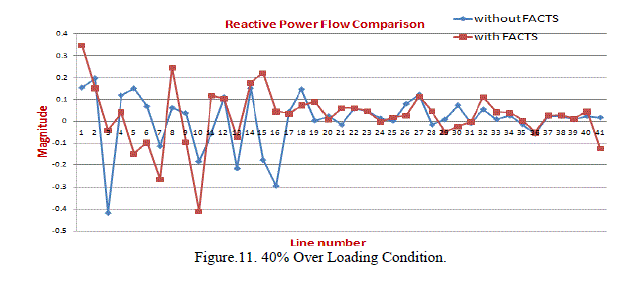
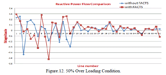
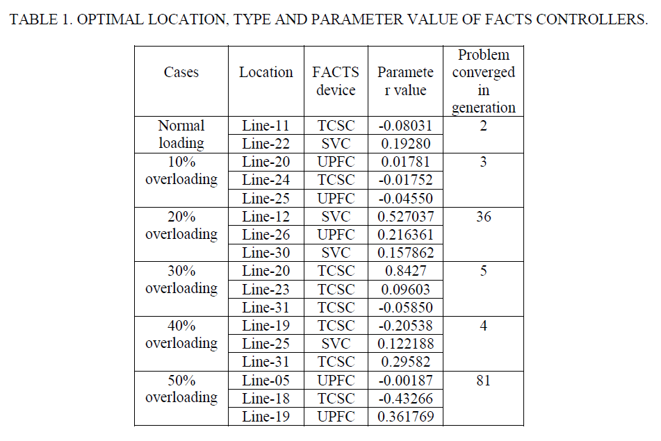
| ïÃÆÃË In order to verify the effectiveness of the proposed method, IEEE 30 bus system is used. Different operating conditions are considered for finding the optimal choice and location of FACTS controllers. |
| • Maximum Generation=200; |
| • Maximum no. of iteration=100; |
| • Population size=60; |
| • Elitism probability=0.150000; |
| • Mutation probability=0.001000; |
| • Crossover probability=0.950000. |
 |
 |
 |
 |
 |
 |
 |
 |
 |
 |
 |
 |
 |
 |
 |
 |
 |
 |
 |
CONCLUSION |
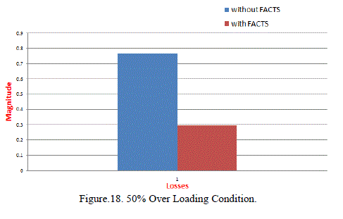
| In this approach Genetic algorithm based optimal placement of FACTS devices in a transmission network is done for the increased loadability of the power system as well as to minimize the transmission loss. Three different type of FACTS devices have considered. It is clearly evident from the result that effective placement of FACTS devices in proper locations can significantly improve system performance. This approach could be a new technique for the installation of FACTS devices in the transmission system. |
References |
|