ISSN ONLINE(2278-8875) PRINT (2320-3765)
ISSN ONLINE(2278-8875) PRINT (2320-3765)
Pokala S Gangadhar1 and Rama Vasantha Adiraju2
|
| Related article at Pubmed, Scholar Google |
Visit for more related articles at International Journal of Advanced Research in Electrical, Electronics and Instrumentation Engineering
A wireless sensor network is proposed for monitoring buildings to assess earthquake damage. The sensor nodes use custom-developed capacitive MEMS strain and 3D acceleration sensors and a low power readout ASIC for a battery life of up to 12 years. The strain sensors are mounted at the base of the building to measure the settlement and plastic hinge activation of the building after an earthquake. They measure periodically or on-demand from the base station. The accelerometers are mounted at every floor of the building to measure the seismic response of the building during an earthquake. They record during an earthquake event using a combination of the local acceleration data and remote triggering from the base station based on the acceleration data from multiple sensors across the building. A low power network architecture was implemented over an 802.15.4 MAC in the 900MHz band. A custom patch antenna was designed in this frequency band to obtain robust links in real-world conditions.
Keywords |
| Accelerometers, Base stations, Buildings, MonitoringSensors, Strain, Wireless sensor networks |
INTRODUCTION |
| Buildings can progressively accumulate damage during their operational lifetime, due to seismic events, unforeseen foundation settlement, material aging, design error, etc. Periodic monitoring of the structure for such damage is therefore a key step in rationally planning the maintenance needed to guarantee an adequate level of safety and serviceability. However, in order for the installation of a permanently installed sensing system in buildings to be economically viable[1], the sensor modules must be wireless to reduce installation costs, must operate with a low power consumption to reduce servicing costs of replacing batteries, and use low cost sensors that can be mass produced such as MEMS sensors. The capability of MEMS and wireless networking for monitoring civil structures is well documented. The presented work addresses all of the above requirements. |
EMBEDDED SYSTEMS |
| Embedded system is application-oriented special computing system which is scalable on both software and hardware. It can satisfy the strict requirement of size, functionality, reliability, cost, and power consumption of the particular application. |
| Examples: PDAs, Smart Phones, IP Phones and Cameras, Autopilot in airplanes, Missile guidance systems, Microwave oven… |
TRENDS IN EMBEDDED MARKET |
| Indian Embedded market (exclusive of services) is worth US $1 billion with annual growth of 50% Current workforce in India is around 40,000 engineers with a future requirement of 80,000 engineers every year. |
| Some of the Major Companies: |
| Intel, General Electric (GE), ATMEL, MOTOROLA, Wipro, Portal Player, Conexant. Many Smaller Companies (Access Control, Smartcard and Biometric Readers, RFID) |
EMBEDDED SYSTEMS - DEBUG TOOLS – ICE |
| In-Circuit Emulators (ICE) is by far the most widely used debug tools for embedded systems. Embedded systems with little or no visibility into the system, pose a challenge to design engineers during the development ICE offers: Break-point features (Simple and Complex), Single-stepping Resource editing and viewing |
SYSTEM ARCHITECTURE |
Network architecture: |
| The monitoring system consists of two types of sensor modules: strain sensing modules and acceleration sensing modules. They are placed in the building as shown in Fig. 1. The strain sensor modules are mounted at the lowest level of the building, to estimate the vertical column loads and any variation due to settlement. Horizontal acceleration is measured by two 3D acceleration sensing modules (where only the two horizontal axes are really required) at each level during an earthquake, allowing analysis of the seismic response of the whole structure. A typical 7-story, 24-column building requires approx. 72 strain sensors (3 per column) and 14 accelerometer modules (2 per floor). The data is wirelessly transmitted to a nearby base station using a line of sight link with a range of >1km. The line of sight link uses directional antennas to improve the link budget, but not so directional that alignment is required, which could pose a problem during seismic events. The receiver base station can store and process the data or forward them, immediately or later, using classical wide area network connection technology. In this way, provided all modules as well as the receiver base station have battery back-up power, the data acquired during seismic events can be properly recorded even in case of outages of the electric power and/or communication networks. |
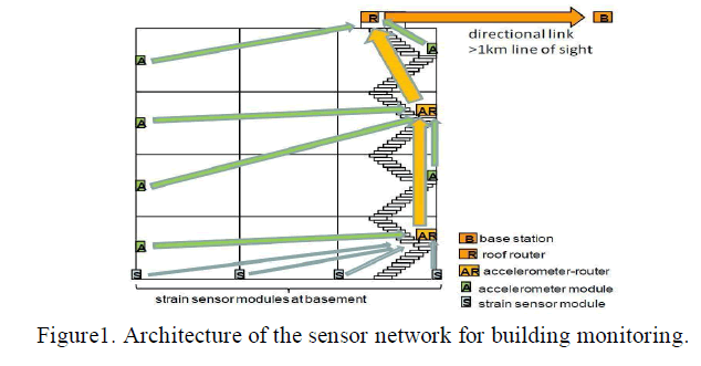 |
| In order to form a robust wireless link from all modules, including the strain sensor modules at the basement of the building, towards the receiver base station, multi-hop network architecture is used as shown in Fig. 1. On the roof of the building a dedicated router module (without sensor) is placed to forward the data between the sensor network and the receiver base station. Some accelerometer modules on intermediate floors can be configured as additional intermediate routers when required to obtain a robust link from all sensor modules in the building towards the roof router module. As shown on Fig. 1, it is recommended to place the router modules in or close to the stairwell for improved vertical floor-tofloor propagation through the building. |
| For lowest power consumption in the sensor modules, the network is implemented using indirect data transfer using polling on top of a standard 802.15.4 MAC. In this way, the end nodes’ radio is powered down most of the time. Only the routers and base station have their receivers constantly on. To avoid rapid battery depletion, the modules with router functionality are mains-powered through an AC/DC adapter, with the battery serving only for back-up power in case mains power is interrupted. The end nodes are battery powered only. |
| The accelerometer and strain sensing variants of the module use the same core components. For installation into the building these components are placed into a standard off-the-shelf plastic casing that can be conveniently mounted on the floor, wall or ceiling using screws, and offering access for sporadic battery replacement if needed. |
HARDWARE: |
| Reference Designs |
| Single board computers |
| In-circuit emulators - very useful |
SOFTWARE: |
| Compilers |
| Assemblers |
| Debuggers |
| Performance & Diagnostic |
COMPONENTS REQUIRED TO IMPLEMENT |
ARM7: |
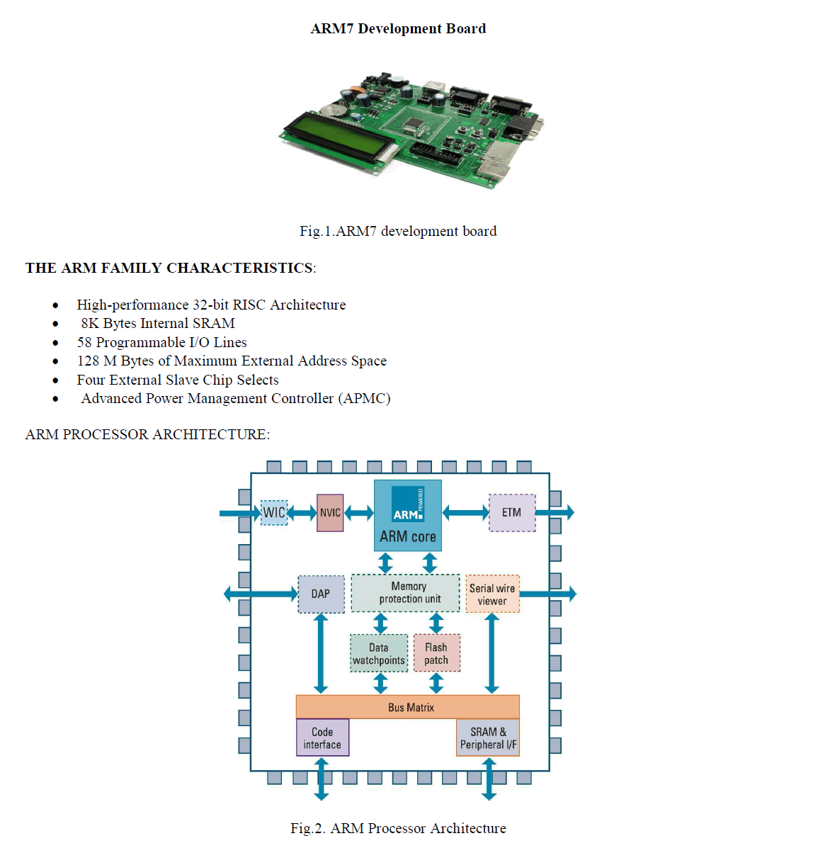
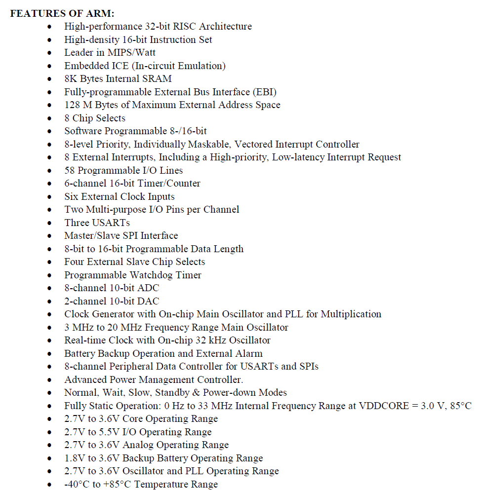
| ARM is a family of instruction set architecture for computer processors based on a reduced instruction set computing (RISC) architecture developed by British company ARM Holdings. |
| A RISC-based computer design approach means ARM processors require significantly fewer transistors than typical CISC x86 processors in most personal computers. This approach reduces costs, heat and power use. Such reductions are desirable traits for light, portable, battery-powered devices—including smart phone, laptop, tablet and notepad computers, and other embedded systems. A simpler design facilitates more efficient multi-core CPUs and higher core counts at lower cost, providing improved energy efficiency for servers. |
 |
 |
MEMS |
| MEMS stands for Micro Electromechanical Systems. MEMS technology is related to microelectronics technology and the integrated circuit industry - there is large overlap of materials and processing techniques. MEMS stands for a novel class of fabrication technology, as well as a class of devices and products. As fabrication technology, MEMS and micromachining can realize precision three dimensional micro structures. Important characteristics of a MEMS device include: |
| 1. Small sizes: optical lithography is used to define features that are as small as 10 nm. Small sizes sometimes lead to favorable scaling of performance characteristics, such as resonant frequency, response speed, sensitivity, etc. |
| 2. Rich performance: transduction blocks and circuits are combined to provide superior performance and signal quality. |
| 3. Low cost: MEMS can potentially achieve very low cost due to bulk fabrication techniques. The cost advantage is especially obvious for large volume products such as consumer electronics (CE). |
| MEMS is a vibrant and sophisticated field. MEMS technology is used to make sensors (devices that measure physical and chemical characteristics), actuators (devices that produce displacement, force, or torque), or structures. Historically, MEMS technology has enabled such products as ink jet printing, automotive airbag sensors, automotive tire pressure sensors, medical pressure sensors, digital light processors, acoustic sensors, accelerometers, and gyroscopes. |
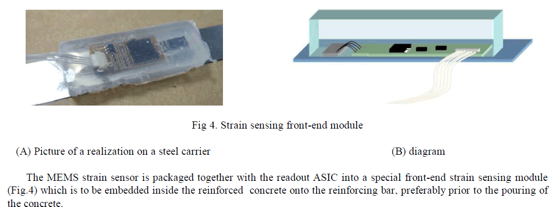
| The MEMS strain sensor is a longitudinal comb finger capacitor. The strain sensor fabrication procedure starts with a SOI wafer with a 500μm thick handle, 50μm thick fingers and 2μm thick oxide layer with 400 fingers in the sensor and it has a sensitivity of 0.133fF/μe. Two anchors were etched-out of the surface to create the necessary clamps to attach the sensor to the rebar of a pillar. The fingers are protected with a borosilicate class cap. |
| The use of custom-developed MEMS sensors and read-out ASIC allows to meet the specific requirements of the building monitoring application and differentiates the presented system from the earlier prototype system. |
 |
ACCELEROMETER MODULES |
| The main trigger for the recording of an acceleration measurement is the detection of the start of an earthquake. The detection can happen in two ways: |
| a) The output of the built-in accelerometer in a selected number of monitoring nodes exceeds a certain minimum threshold, during a certain minimum time; these monitoring nodes alert the base station which will decide whether to wake up the entire network of acceleration sensing nodes over the radio The monitoring nodes are selected based on their location and amount of environmental noise; groundlevel nodes may be suitable candidates, provided they are sufficiently far removed from disturbance sources such as heavy traffic. |
| b) An external source of earthquake detection can be coupled to the base station, which can use such information in addition to possible information from monitoring nodes to decide whether to wake up the entire network or not. |
STRAIN SENSOR MODULES |
| The main measurement scenario for the strain sensor is a periodic readout. Samples are taken at a configurable sample rate between 2 seconds and 18 hours. The strain sensor modules use a radio polling interval of 60 seconds. This also allows manual wake-up functionality from the base station, again useful for monitoring and testability reasons. Unlike for the accelerometers, in the case of the strain sensors the sensor and read-out ASIC can be entirely shut down between measurements. This results in a lower power consumption and longer battery life. Since a typical building requires many more strain sensors than accelerometer modules, it is useful for the strain sensors to have the longest battery service life. |
GLOBAL SYSTEM FOR MOBILE COMMUNICATION (GSM) |
INTRODUCTION TO GSM: |
| Global system for mobile communications (GSM) is the most popular standard for mobile Phones in the world. GSM service is used by over 1.5 billion people across more than 210 Countries and territories. The ubiquity of the GSM standard makes international roaming very common between mobile phone operators, enabling subscribers to use their phones in many parts of the world. GSM differs significantly from its predecessor, in that both signalling and speech channels, as there are digital, which means that it is considered a second generation (2G) mobile phone system. This fact has also meant that data communication was built into the system. From very early on, GSM is an open standard which is currently developed by the 3GPP. |
 |
ABOUT SMS: |
| SMS stands for short message service. Simply put, it is a method of communication that sends text between cell phones, or from a PC or handheld to a cell phone. The “short” part refers to the maximum size of the text messages: 160 characters (letters, numbers or symbols in the Latin alphabet). For other alphabets, such as Chinese, the maximum SMS size is 70 characters. |
| Even if we are not talking on our cell phone, our phone is constantly sending and receiving information. It is talking to its cell phone tower over a pathway called a control channel. |
| The reason for this chatter is so that the cells as we move around. Every so often, our phone and the tower will exchange a packet of data that lets both of them know that everything is OK. |
 |
| GSM AT Commands: |
| AT commands are instructions used to control a modem. AT is the abbreviation of ATtention. Every command line starts with "AT" or "at". That's why modem commands are called AT commands. Many of the commands that are used to control wired dial-up modems, such as ATD (Dial), ATA (Answer), ATH (Hook control) and ATO (Return to online data state), are also supported by GSM/GPRS modems and mobile phones. Besides this common AT command set, GSM/GPRS modems and mobile phones support an AT command set that is specific to the GSM technology, which includes SMS-related commands like AT+CMGS (Send SMS message), AT+CMSS (Send SMS message from storage), AT+CMGL (List SMS messages) and AT+CMGR (Read SMS messages). |
| Note that the starting "AT" is the prefix that informs the modem about the start of a command line. It is not part of the AT command name. For example, D is the actual AT command name in ATD and +CMGS is the actual AT command name in AT+CMGS. However, some books and web sites use them interchangeably as the name of an AT command. |
| Here are some of the tasks that can be done using AT commands with a GSM/GPRS modem or mobile phone: |
| Get basic information about the mobile phone or GSM/GPRS modem. For example, Name of manufacturer (AT+CGMI), model number (AT+CGMM), IMEI number (International Mobile Equipment Identity) (AT+CGSN) and software version (AT+CGMR). |
| Get basic information about the subscriber. For example, MSISDN (AT+CNUM) and IMSI number (International Mobile Subscriber Identity) (AT+CIMI). |
| Get the current status of the mobile phone or GSM/GPRS modem. For example, mobile phone activity status (AT + CPAS), Mobile network registration status (AT+CREG), radio signal strength (AT+CSQ), battery charge level and battery charging status (AT+CBC). |
| Establish a data connection or voice connection to a remote modem (ATD, ATA, etc.). |
| Send and receive fax (ATD, ATA, AT+F*). |
| Send (AT+CMGS, AT+CMSS), read (AT+CMGR, AT+CMGL), write (AT+CMGW) or delete (AT+CMGD) |
| SMS messages and obtain notifications of newly received SMS messages (AT+CNMI). |
| Read (AT + CPBR), write (AT + CPBW) or search (AT + CPBF) phonebook entries. Perform security-related tasks, such as opening or closing facility locks (AT+CLCK), checking whether a facility is locked (AT+CLCK) and changing passwords (AT+CPWD).(Facility lock examples: SIM lock [a password must be given to the SIM card every time the mobile phone is switched on] and PH-SIM lock [a certain SIM card is associated with the mobile phone. To use other SIM cards with the mobile phone, a password must be entered.]) |
| Control the presentation of result codes / error messages of AT commands. For example, you can control whether to enable certain error messages (AT+CMEE) and whether error messages should be displayed in numeric format or verbose format (AT+CMEE=1 or AT+CMEE=2). |
| Get or change the configurations of the mobile phone or GSM/GPRS modem. For example, change the GSM network (AT+COPS), bearer service type (AT+CBST), radio link protocol parameters (AT+CRLP), SMS center address (AT+CSCA) and storage of SMS messages (AT+CPMS). |
| Save and restore configurations of the mobile phone or GSM/GPRS modem. For example, save (AT+CSAS) and restore (AT+CRES) settings related to SMS messaging such as the SMS centre address. |
SWITCH |
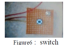
| A push button or simply button is a simple switch mechanism for controlling some aspect of a machine or a process. Buttons are typically made out of hard material, usually plastic or metal. The surface is usually flat or shaped to accommodate the human finger or hand, so as to be easily depressed or pushed. Buttons are most often biased switches, though even many un-biased buttons require a spring to return to their un-pushed state. |
| In industrial and commercial applications, push buttons can be connected together by a mechanical linkage so that the act of pushing one button causes the other button to be released. In this way, a stop button can “force” a start button to be released. This method of linkage is used in simple manual operations in which the machine or process have no electrical circuits for control. |
 |
FINAL RESULTS |
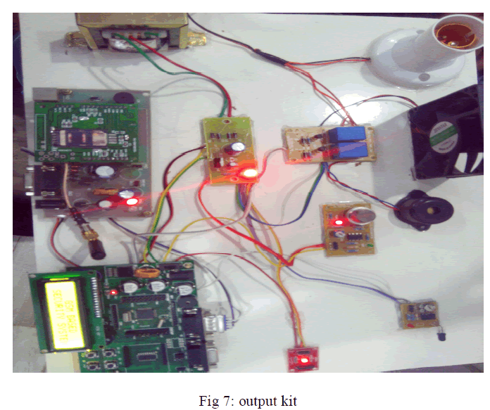
| Thus from our idea we can monitor the building efficiency and to guarantee an adequate level of safety and serviceability |
 |
CONCLUSION |
| The presented wireless system for building monitoring takes advantage of the unique features of custom-developed MEMS sensors and read-out ASIC combined with an optimized network and module architecture, to realize a solution which offers long battery lifetime and potentially low cost in manufacturing, installation and maintenance, while providing high-quality sensor data at the right time. |
References |
|