Keywords
|
| Multilevel Inverter, Pulse Width Modulation, Space vector pulse Width Modulation, Sinusoidal Pulse Width Modulation. |
INTRODUCTION
|
| Numerous industrial applications require higher power apparatus in recent years. Some medium voltage motor drives and utility applications require medium voltage and megawatt power level. A multilevel power converter structure has been introduced as an alternative in high power and medium voltage situations Subsequently, several multilevel converter topologies have been developed.A multilevel converter not only achieves high power ratings but also enables the use of renewable energy sources. The advantages of three-level Inverter topology over conventional two-level topology are 1)The voltage across the switches is only one half of the DC source voltage 2)The switching frequency can be reduced for the same switching losses 3)The higher output current harmonics are reduced by the same switching frequency. |
| The cascaded H bridge inverter has the advantage of a reduction in switch count and more effective utilization of the natural switching speed and voltage-blocking characteristics of the different types of power electronic devices that are used. The most common strategy used for the cascaded H bridge inverter is the phaseshifted carrier PWM, which provide improved harmonic performance when each single-phase inverter is controlled using three-level modulation [1].Although the cascaded H bridge inverter has an inherent self-balancing capability, because of the losses in circuit component and limited controller resolution, a slight voltage imbalance can occur. The simple control block with PI regulator to adjust the trigger angle and to ensure zero steady-state error between the reference dc voltage and the dc-bus voltage can ensure the dc voltage balance , reactive and harmonic compensations [2].An automatic voltage balance can be achieved by supplying voltage to cascaded H bridge inverter by using a high-frequency link which generates all the isolated dc supplies. Therefore low and constant THD at all operating ranges can be obtained [3]. The cascaded H bridge multilevel inverter can be used for high power applications with novel MMC-based frequency changing conversion scheme[4].The modulation methods used in multilevel inverters can be classified according to switching frequency. The existing system used Space vector PWM contol with less number of sectors whereas in proposed system number of sectors used is more to the THD |
PULSE WIDTH MODULATION
|
| The dc input to the inverter is “chopped” by switching devices in the inverter (bipolar transistors, thyristors, Mosfet, IGBT …etc).The amplitude and harmonic contents of the ac waveform are controlled by controlling the duty cycle of the switches. This is the basic of the pulse width modulation (PWM) techniques. There are several PWM techniques each has itsown advantages and also disadvantages. The basicPWM techniques are described briefly in thefollowing subsections. The considered PWMtechniques are: |
| 1) Sinusoidal PWM |
| 2) Hysteresis band current control |
| 3) Space-Vector PWM |
| A. Sinusoidal PWM |
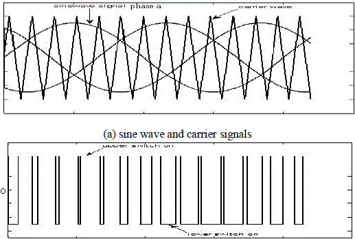
| The most popular PWM approach is the sinusoidalPWM. In this method a triangular (carrier) wave iscompared to a sinusoidal wave of the desiredfundamental frequency and the relative levels of thetwo signals are used to determine the pulse widthsand control the switching of devices in each phaseleg of the inverter. |
| B. Hysteresis-band current control |
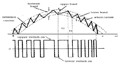
| In hysteresis-band current control the actual current tracks the form of command current within a hysteresis band. In this approach the reference current wave is compared to the actual current wave thus producing the current error .When the current error exceeds a predefined hysteresis band, the upper switch in the half-bridge is turned off and the lower switch is turned on. As the current error goes below the hysteresis band, the opposite switching takes place. The principle of hysteresis band current control is illustrated in Fig. 3.Hysteresis-band current control is very popularbecause it is simple to implement, has fast transientresponse, direct limiting of device peak current and practical insensitivity to machine parameters becauseof the elimination of any additional currentcontrollers. However, PWM frequency is not fixedwhich results in non-optimal harmonic ripple inmachine current. |
| C. Space vector pulse width modulation |
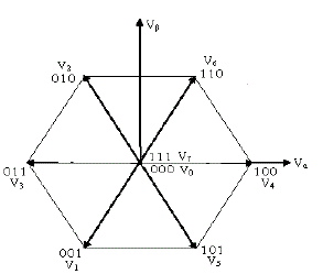
| Space vector PWM refers to a special switchingscheme of the six power semiconductor switches of a three phase power converter.Space vectorPWM (SVPWM) has become a popular PWMtechnique for three-phase voltagesource inverters inapplications such as control of induction andpermanent magnet synchronous motors. Thementioned drawbacks of the sinusoidal PWM andhysteresis-band current control are reduced usingthis technique. Instead of using a separate modulatorfor each of the three phases the complex reference voltage vectorsprocessed as a whole. Therefore, the interactionbetween the three motor phases is considered. It hasbeen shown, that SVPWM generates less harmonicdistortion in both output voltage and current appliedto the phases of an ac motor and provides a moreefficient use of the supply voltage in comparisonwith sinusoidal modulation techniques. |
SOFTWARE IMPLEMENTATION OF SPACE VECTOR PWM
|
| Space vector PWM can be implemented by the following steps: |
| 1) Determine,,and angle(Vd,Vq,Vref,α). |
| 2) Determine the time duration T 1T2T0 |
| 3) Determine the switching time of each MOSFET |
| 1)The Vd, Vq, Vref, and angle (α) can be determined from following steps |
| The voltage vectors on the alpha and beta axis can then be described as: |
 .................(1) .................(1) |
| The magnitude and angle of the reference vector is: |
 ..............(2) ..............(2) |
 .................(3) .................(3) |
| 2) Determine time duration T1, T2, T0 |
| The switching time duration for T1,T2,T0 is given below |
 ...........(4) ...........(4) |
 ..............(5) ..............(5) |
 .............(6) .............(6) |
3) Determine the switching time of each MOSFET
|
RESULTS AND DISCUSSIONS
|
| The main aim of any modulation technique is to obtain variable output having maximum fundamental component with minimum harmonics. The objective of Pulse Width Modulation techniques is enhancement of fundamental output voltage and reduction of harmonic content in Three Phase Voltage Source Inverters. In this paper Space Vector PWM techniques for different levels are compared in terms of Total Harmonic Distortion (THD). |
Parameters of Multilevel inverter
|
| A Simulation of SVPWM |
| Space vector PWM is an advanced technique used for variable frequency drive applications. It utilizes dc bus voltage more effectively and generates less THD in the Three Phase Cascaded H bridge inverter. SVPWM utilize a chaotic changing switching frequency to spread the harmonics continuously to a wide band area so that the peak harmonics can be reduced greatly. Simulation has been carried out by varying the modulation index between 0 and 1. Finally performance of SVPWM is improved in fivel level with 12 sector when compared to three level inverter with 6 sector. |
| The Block Diagram of Space Vector Pulse width modulated inverter fed RL load is shown in Figure 5. |
| In SVPWM methods, the voltage reference is provided using a revolving reference vector. In this case magnitude and frequency of the fundamental component in the line side are controlled by the magnitude and frequency, respectively, of the reference voltage vector. Space vector modulation utilizes dc bus voltage more efficiently and generates less harmonic distortion in a three phase voltage source inverter and multi level inverter. |
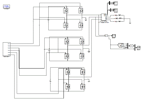
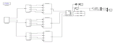
| The Block Diagram of five level Cascaded H bridge inverter using Space Vector Pulse width modulation is shown in Figure-12 |
| The above block diagram shows that software implementation of cascaded H bridge inverter with Space Vector PWM.The Waveform of three level and five level cascaded H bridge inverter is shown in the fig 8and fig 9 |
| The phase voltage of Three level cascaded H bridge inverter is shown in the fig 8 Fig 8. |
| The phase voltage of Five level cascaded H bridge inverter is shown in the fig 9 |
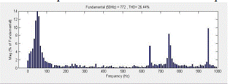
| The FFT analysis of three and five level cascaded H bridge inverter withSVPWM is shown in the fig 10,fig 11. From which we five level multilevel inverter produces THD of 14.38% when compared to three level of 26.44% |
CONCLUSIONS
|
| Space vector Modulation Technique has become the most popular and important PWM technique for Three Phase Voltage Source Inverters for the control of AC Induction, Brushless DC, Switched Reluctance and Permanent Magnet Synchronous Motors. In this paper first comparative analysis of Space Vector PWM with different sectors is carried out. The Simulation study reveals that SVPWM gives 13.58% THD for seven level and 26.4 % for three level cascaded H bridge inverterenhanced fundamental output with better quality i.e. lesser THD compared to SVPWM.SVPWM are implemented in MATLAB/SIMULINK software. SVPWM utilize a changing carrier frequency to spread the harmonics continuously to a wideband area so that the peak harmonics are reduced |
Tables at a glance
|
 |
 |
| Table 1 |
Table 2 |
|
Figures at a glance
|
 |
 |
 |
 |
| Figure 1 |
Figure 2 |
Figure 3 |
Figure 4 |
 |
 |
 |
 |
| Figure 5 |
Figure 6 |
Figure 7 |
Figure 8 |
 |
 |
 |
 |
| Figure 9 |
Figure 10 |
Figure 11 |
Figure 12 |
|
References
|
- Brendan Peter, McGrath and Donald Grahame Holmes (2002) ’Multicarrier PWM Strategies for Multilevel Inverters’ IEEE, Transactions onIndustrial Electronics, Volume 49, no.4, pp .42-52
- Jose Rodriquez, Jih-Sheng Lai and Fang ZhengPeng(2002)‘Multilevel Inverters: A Survey of Topologies Controls, and Applications’ IEEE,Transactions on Industrial Electronics, volume 49, no. 4, pp. 87-95.
- Javier Pereda and Juan Dixon (2011)’High Frequency Link: A Solution for Using Only One DC Source in Asymmetric Cascaded MultilevelInverters’ IEEE, Transactions on Industrial Electronics, volume 58, no. 9, pp. 432-440.
- Diego Soto, Ruben Pena, Roberto Cardenas, Jon Clare and Patrick Wheeler, “A Cascade Multilevel Frequency Changing converter for High-Power Applications”.
- Mohamed Hilmy, MahrousE.Ahmed, Mohamed Orabiand Mohamed ElNemr, (2010)’Modeling and Control of Direct Drive Variable SpeedStand-Alone Wind Energy Conversion Systems’, Proceedings of the 14th International Middle East Power Systems Conference (MEPCON’ 10),volume 87,no 7 ,pp. 567-576
- BandaruUrmila,Subbarayudu D.(2011) ‘Optimized SVPWM for Multilevel Inverter’ Innovative Systems Design and Engineering ISSN 2222-2871 Vol 2, pp. 75-82
- Amit Kumar Gupta, Ashwin M. Khambadkone(2007)’A Space Vector Modulation Scheme to Reduce Common Mode Voltage for CascadedMultilevel Inverters’ IEEE Transactions on Power Electronics, Vol. 22, NO. 5, pp .45-56
- Hind Djeghloud, HocineBenalla(2004)’Space Vector Pulse Width Modulation Applied to the Three-Level Voltage Inverter’IEEETrans.Power Electron., Vol. 19, pp .732-738.
- AbdelfatahKolli, Alexandre De Bernardinis, Eric Labouré, and Gérard Coquery (2003)’Space-Vector PWM Control Synthesis for an HBridgeDrive in Electric Vehicles’IEEE Transactions on Vehicular Technology, vol. 62, no. 6, pp .567-587
- Di Zhao, G. Narayanan and Raja Ayyanar(2004)’Switching Loss Characteristics of Sequences Involving ActiveState Division in SpaceVector Based PWM’IEEE Transactions on Power Electronics, Vol. 22, NO. 5,pp .786-795
- Amit Kumar GuptaandAshwin M. Khambadkone(2007) ‘A General Space Vector PWM Algorithm for Multilevel Inverters, IncludingOperation in Overmodulation Range’ IEEE Transactions on Power Electronics, vol. 22, no. 2, pp. 456-464
- Bindeshwarsingh, Nupurmittal,Dr.Verma K.S , Dr. Deependrasingh(2012)’Multi-level inverter: A Literature Survey on Topologies andControl Strategies’International Journal of Reviews in Computing,pp .56-65
- PardasaniHitendra.K ,AroraKapildev.N(2011) ‘Simulation of three level inverter Sinusoidal pulse width modulation technique by MATLAB’ Proceedings of the National Conference on Recent Trends in Engineering & Technology, pp .98- 110
- G.AnandBalaj,T.ArunSrinivasDr.M.Sasikumar(2012) ‘Modeling and Simulation Analysis of Seven Level Cascaded Multi String Invertersfor Grid Integrated Systems Proceedings of the IOSR Journal of Engineering (IOSRJEN), Vol. 2 ,pp. 156-170
|