Keywords
|
| Power Quality, transient and dynamic stability, Reliability of supply, Voltage sags and voltage swells, FACTS devices. |
INTRODUCTION
|
| The power system should have 15-20% of reserve power available to be able to meet any customer demand. If there is no or insufficient reserve capacity and the load level exceeds the power generation level, a decline in voltage at the consumer side will appear which would upset the normal operation of the users ‘machines and electrical devices or even cause them to fail. For this reason it is essential for the normal functioning and development of each social community to have reliable national and local electric power systems with capacities exceeding the actual energy demand by at least 15% according to work done by Yurek (1999). Unfortunately, however, only rich and advanced modern countries possess such high-grade energy systems. The power systems of most countries in the world have capacities that only just meet their energy demands, and in some cases are simply inadequate. This hunger for electricity is very often a limiting factor for the economic and social development of a country. The electric energy needs of the population, industry, agriculture, transport, etc. increase every year, and the claims for high-quality electric power become ever more demanding in relation to the increasing automation and computerization of the national economy. |
TECHNOLOGIES OF ENERGY STORAGE SYSTEMS
|
| Electrical energy in an ac system cannot be stored electrically. However, energy can be stored by converting the ac electricity and storing it electromagnetically, electrochemically, kinetically, or as potential energy. Each energy storage technology usually includes a power conversion unit to convert the energy from one form to another. It has been established that the different forms of motion e.g. mechanical, thermal, electromagnetic, gravitational, chemical, etc.are converted into one another following definite quantitative ratio. To allow measurement of the various forms of motion by a unified measuring unit, the term energy has been introduced. The electrical energy is determined from the product of the voltage and the quantity of charge that passes through an electrical device (load).The work done per unit time is called power. Electrical power is determined from the product of voltage and current. The different energy storage systems are: |
| IIa. Superconducting magnet energy storage systems (SMES) |
| IIb. Flywheel Energy Storage Systems (FESS) |
| IIc. Super Capacitor Energy Storage systems (SCES) |
| IId. Battery Energy Storage Systems (BESS) |
a. Superconducting Magnetic Energy Storage Systems (SMES)
|
| The SMES recharges within minutes and can repeat the charge/discharge sequence thousands of times without any degradation of the magnet. Recharge time can be accelerated to meet specific requirements, depending on system capacity. |
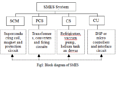
| This is an energy storage device with a lot of promise in effectiveness in terms of capacity and efficiency. SMES units use liquid helium to keep the coil of niobium-titanium at 4.2K, the temperature required for its material to become superconducting. The block diagram is shown in fig1. |
Operation:
|
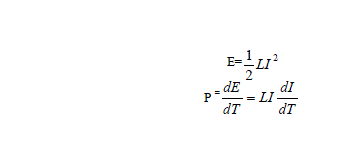
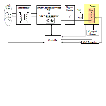
| An SMES unit consists of a large superconducting coil at the cryogenic temperature. This temperature is maintained by a cryostat or Dewar that contains helium or nitrogen liquid vessels. A power conversion/ conditioning system (PCS) connects the SMES unit to an ac power system, and it is used to charge/discharge the coil. Two types of power conversion systems are commonly used. One option uses a current source converter (CSC) to both interface to the ac system and charge/discharge the coil. The second option uses a voltage source converter (VSC) to interface to the ac system and a dc–dc chopper to charge/discharge the coil. The VSC and dc–dc chopper share a common dc bus. The modes of charge/discharge/standby are obtained by controlling the voltage across the SMES coil. The SMES coil is charged or discharged by applying a positive or negative voltage across the superconducting coil. The inductively stored energy (in joules) which is shown below. |
 |
| Performance Characteristics: |
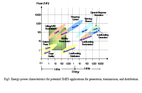
| SMES’ efficiency and fast response capability (MW/millisecond) have been, and can be further exploited in applications at all levels of electric power systems. Some of them are: |
| ïÃâ÷ Frequency support (spinning reserve) during loss of generation. |
| ïÃâ÷ Enhancing transient and dynamic stability. |
| ïÃâ÷ Dynamic voltage support (VAR compensation). |
| ïÃâ÷ Improving power quality. |
| ïÃâ÷ Increasing transmission line capacity, thus enhancing overall security and of reliability Power systems. |
| ïÃâ÷ It has efficiency greater than or equal to 90%. |
| Applications of SMES: |
| ïÃâ÷ An advantage of SMES is that power is available almost instantaneously, and very high power output is provided for a brief period of time. There is no loss of power, and are no moving parts. |
| ïÃâ÷ Already dramatically used in such applications as high-speed, magnetic-levitated trains, superconductors are also being developed for use in microelectronics and communications. |
| Cost: |
| SMES cost approximately $300/kW to $509/kW. It is worth noting that it is difficult to compare the cost of SMES to other storage devices due to its scales and purpose. Superconductor is expected to decline by almost 30% which could make SMES an even more attractive option for network improvements. |
| Advantages: |
| The most important advantage of SMES is that the time delay during charge and discharge is quite short. Power is available almost instantaneously and very high power output can be provided for a brief period of time. |
| Disadvantages: |
| The most significant drawback of SMES is its sensitivity to temperature. As discussed the coil must be maintained at an extremely low temperature in order to behave like a superconductor. |
| Future: |
| Immediate focus will be in developing small SMES devices in the range of 1 MW to 10 MW for the power quality market which has foreseeable commercial potential. A lot of work is being carried out to reduce the capital and operating costs of highâÃâ¬ÃÂtemperature SMES devices, as it is expected to be the commercial superconductor of choice once manufacturing processes are more mature, primarily due to cheaper cooling. There is a lot of market potential for SMES due to its unique application characteristics, primarily in transmission upgrades and industrial power quality. However, one of the greatest concerns for SMES is its reliability over a long period of time. |
b. Flywheel Energy Storage Systems (FESS)
|
| A flywheel is an electromechanical device that couples a motor generator with a rotating mass to store energy for short durations. Flywheel energy storage (FES) System is a device which works by accelerating a rotor (flywheel) to a very high speed and maintaining the energy in the system as rotational energy. When energy is extracted from the system, the flywheel's rotational speed is reduced as a consequence of the principle of conservation of energy; adding energy to the system correspondingly results in an increase in the speed of the flywheel. |
| Operation: |
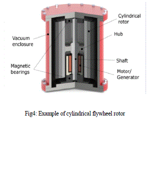
| The FES devices store energy in the form of kinetic energy in the high-speed rotors. The main function of a flywheel is to smoothen out variations in the speed of a shaft caused by torque fluctuations. Flywheel absorbs mechanical energy by increasing its angular velocity and delivers the stored energy by decreasing its velocity. In most cases, a power converter is used to drive the electric machine to provide a wider operating range. Stored energy depends on the moment of inertia of rotor and square of rotational velocity of the flywheel. Moment of inertia (J) depends on the radius, mass, and height (length) of the rotor. The rotor can be modelled as a rotating hollow cylinder. The kinetic energy T stored is given by |
 |
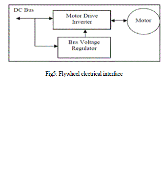
| Where J is polar moment of inertia about axis of rotation and ω is the angular velocity. The energy storage capability of flywheels can be improved either by increasing the moment of inertia of flywheel or by turning it at higher rotational velocities, or both. Fig.3 shows the flywheel electrical interface. |
| Performance Characteristics: |
| ïÃâ÷ Flywheels can respond to many power quality issues such as frequency deviation, temporary interruptions, voltage sags, and voltage swells. |
| ïÃâ÷ FESS constitutes short term storage systems, which are generally sufficient to improve the power quality compared to other ways of storing electricity, FES systems have long lifetimes (ranges from in excess of 105, up to 107, cycles of use), high energy densities (100-130 Wh/kg, or 360-500 kJ/kg), and large maximum power outputs. |
| Applications: |
| Flywheels have an extremely fast dynamic response, a long life, require little maintenance, and are environmentally friendly. They have a predicted lifetime of approximately 20 years or tens of thousands of cycles. As the storage medium used in flywheels is mechanical, the unit can be discharged repeatedly and fully without any damage to the device. Consequently, flywheels are used for power quality enhancements such as Uninterruptable Power Supply (UPS), capturing waste energy that is very useful in electric vehicle applications and finally, to damper frequency variation, making FES very useful to smooth the irregular electrical output from wind turbines. And also used in Rail vehicles, rail electrification etc. |
| Cost: |
| At present, FES systems cost between $200/kWh to $300/kWh for lowâÃâ¬ÃÂspeed flywheels, and $25,000/kWh for highâÃâ¬ÃÂspeed flywheels. However, FES have a longer lifespan, require lower maintenance, have a faster charge/discharge, take up less space and have fewer environmental risks. |
| Advantages: |
| ïÃâ÷ Flywheels are not as adversely affected by temperature changes, can operate at a much wider temperature range, and are not subject to many of the common failures of chemical rechargeable batteries. |
| ïÃâ÷ Another advantage of flywheels is that by a simple measurement of the rotation speed it is possible to know the exact amount of energy stored. |
| Disadvantages: |
| As flywheels are optimized for power or storage capacities, the needs of one application can often make the design poorly suited for the other. Consequently, low speed flywheels may be able to provide high power capacities but only for very short time period, and high speed flywheels the opposite. Also, as flywheels are kept in a vacuum during operation, it is difficult to transfer heat out of the system, so a cooling system is usually integrated with the FES device. Finally, FES devices also suffer from the idling losses: when flywheels are spinning on standby, energy is lost due to external forces such as friction or magnetic forces. As a result, flywheels need to be pushed to maintain its speed. However, these idling losses are usually less than 2%. |
| Future: |
| Low maintenance costs and the ability to survive in harsh conditions are the core strengths for the future of flywheels. Flywheels currently represent 20% of the $1 billion energy storage market for UPS. Due to its size and cycling capabilities, FES could establish even more within this market if consumers see beyond the larger initial investment. As flywheels require a preference between optimisation of power or storage capacity, it is unlikely to be considered a viable option as a sole storage provider for power generation applications. |
Super Capacitor Energy Storage Systems (SCES)
|
| Super Capacitor: |
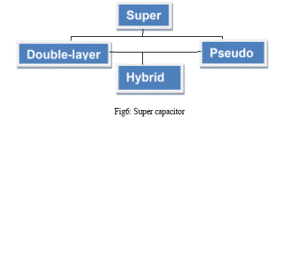
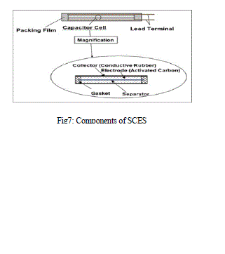
| Electrical double-layer capacitors (EDLC) are, together with pseudo capacitors, part of a new type of electrochemical capacitors called super capacitors, also known as ultra capacitors. |
| Operation: |
| Capacitors consists of two parallel plates that are separated by a dielectric insulator, see Figure 5âÃâ¬ÃÂ15. The plates hold opposite charges which induces an electric field, in which energy can be stored. The energy within a capacitor is given by, |
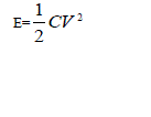 |
| Where E is the energy stored within the capacitor (in Joules), V is the voltage applied, and C is the capacitance found from |
 |
| where A is the area of the parallel plates, d is the distance between the two plates, εr is the relative permittivity or dielectric constant, and ε0 is the permittivity of free space (8.854 x 10⁻¹² F/m). Therefore, to increase the energy stored within a capacitor, the voltage or capacitance must be increased. Super capacitors are created by using thin film polymers for the dielectric layer and carbon nano tube electrodes. They can be connected in series or in parallel. SCES systems usually have energy densities of 20 MJ/m3 to 70 MJ/m3, with an efficiency of 95%. |
| Why can we use super capacitors for energy storage? |
| ïÃâ÷ Super capacitors are unique electrical storage devices that can store much more energy than conventional capacitors, and offer higher power density than batteries. |
| ïÃâ÷ Batteries are widely used for energy storage in industrial and consumer electronics devices because of their high energy density, but are limited in their power density. With its limited power the battery often cannot supply the required power while still retaining its open circuit voltage. When high power is required in battery operated devices (i.e. in pulse applications), the combination of the super capacitor connected in parallel to the battery gives the advantages of both, enhancing the performance of the battery and extending its life, exploiting the batteries to its maximum potential. The super capacitor connected to the battery in parallel produces a voltage damping effect - low impedance super capacitors can be charged in seconds with a low current during standby times between high current pulses. Adding the super capacitor to the battery in parallel decreases the voltage drop, leading to: |
| ïÃâç Better energy and power management |
| ïÃâç Battery life and operational range extension |
| ïÃâç Superior energy density in the battery |
| Applications: |
| Although the energy density is smaller, SCES is a very attractive option for some applications such as hybrid cars, cellular phones, and load levelling tasks. SCES is primarily used where pulsed power is needed in the millisecond to second time range, with discharge times up to one minute. |
| Cost: |
| SCES costs approximately $12,960/kWh to $28,000/kWh. Therefore, large scale applications are not economical using SCES. |
| Advantages: |
| ïÃâ÷ Long life time |
| ïÃâ÷ Little degradation over hundreds of thousands of cycles |
| ïÃâ÷ Enhances pulse current handling by parallel connection with an electro-chemical battery |
| ïÃâ÷ Reduces voltage drop compared to battery operated device with no Super Capacitor |
| ïÃâ÷ Much slower ageing and degradation compared to batteries |
| ïÃâ÷ Meets environmental standards |
| ïÃâ÷ Improved safety |
| Disadvantages |
| ïÃâ÷ Low energy density |
| ïÃâ÷ Serial connections are needed to obtain higher voltages |
| ïÃâ÷ SCES has a very low energy storage density leading to very high capital costs for large scale applications. Also, they are heavier and bulkier than conventional batteries |
| Future: |
| Despite the small energy storage densities on offer, the exceptional life and cycling capabilities, fast response and good power capacity (up to 1 MW) of super capacitors means that they will always be useful for specific applications. However, it is unlikely that SCES will be used as a sole energy storage device. One longâÃâ¬ÃÂterm possibility involves combining SCES with a battery based storage system. SCES could smooth power fluctuations, and the battery provides the storage capacity necessary for longer interruptions. However, other technologies (such as flow batteries) are more likely to be developed for such applications. As a result, the future of SCES is likely to remain within specific areas that require a lot of power, very fast, for very short periods. |
d. Battery Energy Storage Systems (BESS)
|
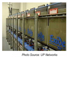
| 1) Batteries are one of the most cost-effective energy storage technologies available, with energy stored electrochemically. Key factors in battery for storage applications include: high energy density, high energy capability, round trip efficiency, cycling capability, life span, and initial cost. Battery technologies under consideration for large-scale energy storage. Lead-acid batteries can be designed for bulk energy storage or for rapid charge/discharge. Mobile applications are favoring sealed lead-acid battery technologies for safety and ease of maintenance. |
| 2) Valve regulated lead-acid (VRLA) batteries have better cost and performance characteristics for stationary applications. |
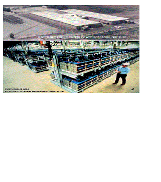
| Lead-acid batteries, have been used in a few commercial and large-scale energy management applications. The largest one is a 40 MWh system in Chino, California, built in 1988. The table below lists and compares the lead-acid storage systems that are larger than 1MWh. |
IMPLEMENTATION OF FACTS WITH ENERGY STORAGE DEVICES
|
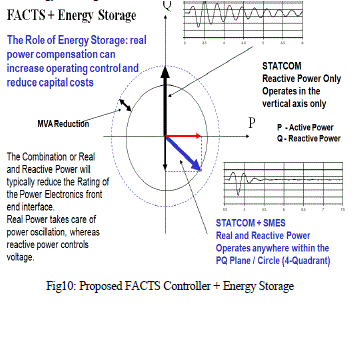
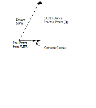
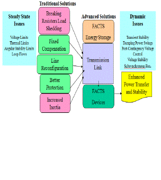
| i. Proposed FACTS Controller + Energy Storage: |
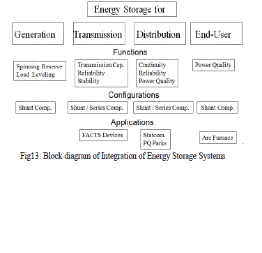
| ii. Integration of Energy Storage Systems into FACTS Devices: |
| ïÃâ÷ FACTS controllers are power electronics based devices that can rapidly influence the transmission system parameters such as impedance, voltage, and phase to provide fast control of transmission or distribution system behavior. |
| ïÃâ÷ FACTS controllers that can benefit the most from energy storage are those that utilize a voltage source converter interface to the power system with a capacitor on a dc bus. This class of FACTS controllers can be connected to the transmission system in parallel (STATCOM), series (SSSC) or combined (UPFC) form, and they can utilize or redirect the available power and energy from the ac system. |
| ïÃâ÷ Without energy storage, FACTS devices are limited in the degree of freedom and sustained action |
| iii. Integration of Energy Storage Systems: |
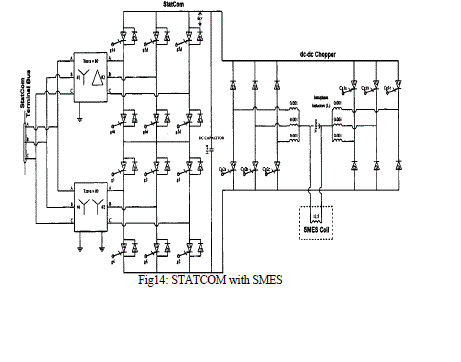
| iii. a. STATCOM with SMES |
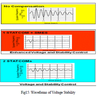
| The performance of a power-electronics -energy-storage-enhanced device is very sensitive to the location with regard to generation and loads, topology of the supply system, and configuration and combination of the compensation device. |
| the STATCOMs in the SMES circuit the stability performance increases. By increasing the number of STATCOMs in the circuit the performance increases so that power quality also increases. |
| iii. b. FACTS with BESS |
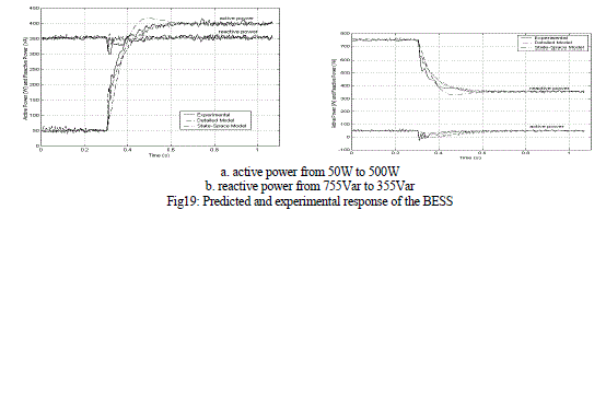
| The principal benefit of the STATCOM for transient stability enhancement is direct through rapid bus voltage control. In particular, the STATCOM may be used to enhance power transfer during low-voltage conditions, which typically predominate during faults, decreasing the acceleration of local generators. An additional benefit is the reduction of the demagnetizing effects of faults on local generation. |
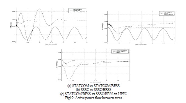
| The active and Reactive power responses are as shown below. |
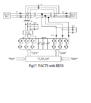
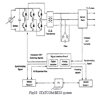
| We can obtain the same results by using following circuit |
| The STATCOM is connected in a circuit which is commanly used with energy storage systems to improve the system performances. |
CONCLUSION
|
| In the changing system of power production more storage systems will be needed in the future. The more renewable energy power plants with fluctuating supply of solar radiation or wind are connected with the grid, the more additional conventional power plants or storage systems are needed to guarantee a balancing of demand and supply of power. FACTS (Flexible AC Transmission Systems) devices which handle both real and reactive power to achieve improved transmission system performance are multi-MW proven electronic devices now being introduced in the utility industry. In this environment, energy storage is a logical addition to the expanding family of FACTS devices. Potential performance benefits produced by advanced energy storage applications improved system reliability, dynamic stability, enhanced power quality, transmission capacity enhancement, area protection, etc.. |
| Energy storage devices can facilitate this process, allowing the utility maximum utilization of utility resources. The new power electronics controller devices will enable increased utilization of transmission and distribution systems with increased reliability. This increased reliance will result in increased investment in devices that make this asset more productive. Energy storage technology fits very well within the new environment by enhancing the potential application of FACTS, Custom Power and Power Quality devices. As deregulation takes place, generation and transmission resources will be utilized at higher efficiency rates leading to tighter and moment-by-moment control of the spare capacities. |
Figures at a glance
|
 |
 |
 |
 |
 |
| Figure 1 |
Figure 2 |
Figure 3 |
Figure 4 |
Figure 5 |
 |
 |
 |
 |
 |
| Figure 6 |
Figure 7 |
Figure 8 |
Figure 9 |
Figure 10 |
 |
 |
 |
 |
 |
| Figure 11 |
Figure 12 |
Figure 13 |
Figure 14 |
Figure 15 |
 |
 |
 |
 |
| Figure 17 |
Figure 18 |
Figure 19 |
Figure 19a |
|
References
|
- Z. Yang, C. Shen, L. Zhang, M. L. Crow, and S. Atcitty, “Integration of a StatCom and battery energy storage,” IEEE Transactions on PowerSystems, vol. 16, no. 2, pp. 254–260, 2001.
- IEEE power engineering society. FACTS application task force, FACTS applications, IEEE Publication 96-TP116-0. R. Kuiava, R. A. Ramos,and N. G. Bretas, “Control design of a STATCOM with energy storage system for stability and power quality improvements,” in Proceedings oftheIEEEInternational Conference on Industrial Technology (ICIT ’09),pp.1–6,February2009.
- K. Malarvizhi and K. Baskaran, “Reactive power compensation and stability analysis of fixed speed wind generators using STATCOMintegrated with energy storage devices,” International Journal of Sustainable Energy, vol. 30, no. 6, pp.367–375, 2011.
- R. J. Nelson, J. Bian, D. G. Ramey, T. A. Lemak, T. R. Rietman, and J. E. Hill, “Transient stability enhancement with FACTS controllers,” inProceedings of the 6th International Conference on AC and DC Power Transmission, pp. 269–274, May 1996. K. K. Sen, “STATCOMSTATICsynchronous compensator: theory, modeling and applications,” IEEE Transactions on Power Delivery, vol. 2, pp. 237–243, 1999.
- P. Taylor, L. Johnson, K. Reichart, P. DiPietro, J. Philip, and P. Butler, “A summary of the state of the art of superconducting
- magnetic energy storage systems, flywheel energy storage systems, and compressed air energy storage systems,” Sandia NationalLabs,SAND99-1854, 1999.
- J. D. Boyles and N. H. Clark, “Technologies for energy storage:
- Flywheels and superconducting magnetic energy storage,” in Proc.2000 IEEE Power Engineering Society Summer Meeting, vol. 3, July 2000,pp. 1548–1550.
- Y. Mitani, K. Tsuji, and Y. Murakami, “Application of superconducting magnet energy storage to improve power system dynamicperformance,” IEEE Trans. Power Systems, vol. 3, pp. 1418–1425,Nov. 1988.
- R.Meinski, R.Pawelek and I.Wasiak, “Shunt Compensation for Power Quality Improvement Using a STATCOM controller ModellingandSimulation”, IEEE Proce, Volume 151, No. 2, March 2004.
- Sustainable Energy Authority of Ireland, 2010,http://www.seai.ie/Publications/Statistics_Publications/SEI_Renewable_Energy_2010_Update/RE_in _Ire_2010update.pdf
- S.C. Smith and P.K. Sen, “Ultracapacitors and Energy Storage:
- Applications in Electrical Power System,” Proceedings of the North American Power Symposium (NAPS), Calgary, Canada, Oct. 2008
|