Research & Reviews: Journal of Engineering and Technology
ISSN: 2319-9873
ISSN: 2319-9873
Tanbir Ibne Anowar*
Department of Electrical and Electronic Engineering, Stamford University, Bangladesh
Received date: 08/10/2018; Accepyed date: 19/12/2018; Published date: 26/12/2018
Visit for more related articles at Research & Reviews: Journal of Engineering and Technology
In this paper, Wireless Power Transfer (WPT) is investigated into the midrange operation considering the 65 cm distance where the power transfer capability is still possible due to the optimum impedance matching. Load side and source side impedance matching network are established and an optimum coupling is found and varied in each of the distance to achieve maximum power transferability. A comparison is done to validate the mathematical explanation with proper physical experiment and measured data confirmed the improvement of +3dB at 60 cm distance between the load and resonator coil.
Critical coupling, Power transfer efficiency, Wireless power transfer, Mutual coupling
The research on Wireless Power Transfer (WPT) technology began since the 1880s with the earliest experiment of WPT which was performed by Nikola Tesla [1-6]. An alternating current of 50 KHz was adopted to lighten an incandescent at a distance in 1899. Since then the idea of Wireless Power Transfer (WPT) has been the topic of research for over a century. The development of WPT technology had been very slow for a long time, until 2007, Marin Soljacic whom from the Massachusetts Institute of Technology (MIT) got a new breakthrough. They use the power source of two meters away lit a 60W light bulb [1-6]. This achievement promoted the development of WPT technology with a big step. During the past decades, with the rapid development of semiconductor and integrated circuit technology, the electronic devices came into our lives rapidly with a growing number of electric wires [7]. These wires have seriously made our life in disorder. The safety and reliability of these wires become worse with longer duration of use. Besides, the frequency plug interface can also shrinkage the lifetime of electrical equipment. Due to the limitations of the wired power supply, people began to look increasingly shift to wireless power.
Wireless Power Transfer (WPT) is an emerging technology that now substantially gaining more interest due to their contribution in technical fields such as biomedical science [8-11], electronic [12-15] and automobile industry [16-19]. A WPT system majorly consists of magnetically coupled coils and matching circuits. The magnetic coupling between the transmitter (TX) and receiver (RX) actually depends on the input and output impedance condition which is inversely related to the distance [20]. Generally, the tunable LC impedance matching network is used to transform the overall circuit impedance, but lossy matching network increases the power loss and lowers the efficiency as well. In this study, a high efficient WPT system is designed using loop size TX and RX coils separated by a multi-turn planer shape repeater coil. The power transfer efficiency is optimized through the tuning of the coupling coefficient. Until now, many efforts have been made to improve the WPT technology as well as its application which can be classified into three categories: electromagnetic induction [21-23], magnetic resonance [24-26], and microwave power transmission [27,28]. Magnetic resonant coupling is considered the most suitable for WPT applications due to its high transmission range and efficiency compare to the induction coupling and microwaves [29]. In resonant coupled WPT, the transfer distance is actually limited due to reduced magnetic coupling with the axial separation between TX and RX coils. The effect of low couplings can be somewhat compensated by employing high-quality factor ‘Q’ (Q=(1/R)(L/C)1/2) TX/RX coils [30]. Nonetheless, in practical WPT system, Q-factor of the coil becomes limited due to the loading effects of source/load resistances and ohmic losses of wire. Furthermore, high Q-factor causes the magnetic field of the circuit to rise due to high reactance and may cause adverse effects on the human body [31-33]. WPT performance depends greatly on its design of TX circuit [34,35]. The position of the coils also greatly affects the impedance mismatch into the system, causing a loss of power transfer [36]. Our proposed tuning method at the optimum position would help the matching between the coils in certain distances. In a previous analysis, many complex circuitry and technique have been brought into account for the WPT system.
In this paper, we investigated the maximum power point tracking of WPT at midrange operation. This is followed by the experimental validation after proper simulation prospect.
Basic WPT Circuit Model of Efficient Power Transfer
A coupled resonance exhibits properties to transfer energy in a system to its maximum case for some certain frequency. A Strong Coupled Magnetic Resonance (SCMR) could deliberately transfer energy into the midrange when both transmitter (TX) and receiver (RX) are tuned to a single frequency. This type of transmission requires a continuous alteration of the induced magnetic field inside both TX and RX coils, thus AC transmission is introduced inside the TX and RX current coil. To maintain a resonant frequency, capacitors are considered both receiving and transmitting sides. So that, at resonant frequency all the power can be transferred as both TX and RX are resonating at the same frequency. ‘Q-factor’ determined for each coil must be high enough to consider a high transmission rate. In WPT, an efficient power transfer requires a matching network between the primary source to load. In Figure 1(a), represents the equivalent circuit and the simple graphical explanation of WPT. If the source and load impedances are RS + jXS and RL + jXL , the power delivered from the source to load becomes maximum when RS = RL and XS = XL For any fixed RS , the output power will become maximized when RS = RL and increases by the condition of RL > RS Total efficiency of the system can be found through the following expression in Eqn. (1).
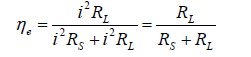 (1)
(1)

Figure 1: (a). Basic equivalent circuit of a WPT system (b) Graphical representation of Efficiency and output power as a function of RL/RS . (2)
From Figure 1(b) the maximum energy efficiency cannot go beyond 50% under this principle, which means half of the power, will be dissipated in the source resistance. Nonetheless, in this paper, an efficient power transfer model is thus considered with the optimum coupling mechanism.
Maximum Energy Efficiency Principle
In a basic concept, when the loss RS is minimized thus the efficiency can be enhanced. In the WPT system, the loss can be minimized in various ways; one of the techniques is to match the impedance. In Figure 1(a), conductive losses are only due to the AC resistance of the conductors and power loss in source resistance. Thus, according to Equation 1, we could use low resistance RS at the source side to increase the energy efficiency of the system. In case of using high frequency, litz wire can be used to reduce the loss ie increasing the efficiency. In WPT, multi coils resonant WPT contributes the simplicity with a considerable trade-off between efficiency and distance. A general model of 3 coil RCWPT model with an intermediate multi-turn coil is depicted in Figure 2(a), TX and RX coils are used with a single turn to avoid the self and parasitic capacitances that can mismatch impedance on both TX and RX sides. Resonating operations are kept in R-L-C series combination at both sides. Targeted Energy transfer is modeled with a total distance (d) between the TX and RX coil. A repeater coil enhanced the distance (where, total distance d=dTX+dRX in Figure 2(a) whereas, PTE degrades sharply by a slight increment of distance. In this study of three coil WPT system, a robust technique of tuning mechanism is described to enhance the system performance. To understand the key interaction between the coils, one can anticipate the coils connected with spring to each another, a weak coupling will provide high efficiency with moderate distance energy transfer and vice versa. High efficiency is achieved at resonance, while all the coils are able to induce magnetic flux to transfer the energy to the load. As the coupling coefficient comes as a function of power transfer and also coupling coefficient depends on variable parameters and distance mainly so that the PTE can be maximized by providing the adequate tuning between the coils. All coils are provided with high-quality factor (Q) and the coupling coefficients are kept low to transfer the power easily. In the circuit arrangement, AC voltage source and Series resistance (RS) represent the class-E PA output, which energizes the TX coil at the driving frequency. As because the loading effect degrades the performance that can be reduced by a factor of ω2M/R (M=mutual inductance) using feeding loops as TX/RX coils with a multi-turn resonator as a magnetic repeater between them [3-5]. The intermediate resonators, relay the magnetic field from TX to RX, and would easily improve the magnetic coupling at long distance. Cross-coupling between TX and RX is ignored due to its small value relative to coupling coefficient between TX and repeater (kTX) coil and repeater to RX coil (kRX).

Figure 2: (a). Schematic of resonant coupled WPT system with a repeater (b). Electrical circuit model of WPT.
To analyze the working model of a simple 3coil structure is shown in Figure 2(b), where all the coils are considered as a flat spiral to avoid the parasitic lumped elements. RPT, Rrep, and RPR are the intrinsic resistance of TX, Repeater and RX coil respectively. R-L and RS are the load and source resistance. Lx and Cx (x=TX, rep and RX) are connected in series. CTX, Crep, and CRX are the resonant capacitors of TX, Repeater and RX coil respectively. Resonant capacitances were kept constant with an operating frequency. CTX is considered as output matching network of class-E PA along with the parasitic capacitance of resonator. Besides this model, an RF power amplifier is designed to get a good gain with high drain efficiency. Considering the Biot-Savart’s Law of current carrying conductor, an alternating current (AC) is introduced by the signal generator to get an oscillating magnetic field that can store the energy in LTX and induced Electro Motive Force (e.m.f) in Lrep and finally transferred into LRX. The mutual inductance between the coils can be found through Neumann’s formula;
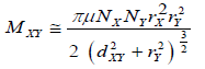 (2)
(2)
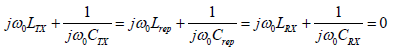
Where, Mxy is the mutual inductance between two coils, Nx, Ny are the turn number of primary and secondary coil respectively, similarly rx, ry is the radius of the primary and secondary coil. dxy is the distance between them. Lumped elements like inductor and capacitor consist of imaginary value which behaves as a lossy element in WPT. Thus, it is required to operate the whole WPT system with its resonant frequency to consider maximum power transfer. In this work, resonant frequency (f0) is kept such as;
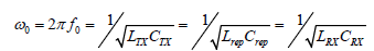 (3)
(3)
According to Kirchhoff’s voltage law (KVL) applied to this electrical circuit model in Figure 2(b) are;
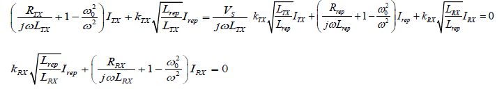 (4-6)
(4-6)
Where, Rx, Lx, Cx, Ix, and kx is the total resistance, coil inductance, resonant capacitance, coil current and coupling coefficient of respective x=TX/RX/rep. Here, RTX=RS+RPT and RRX=RL+RPR, at resonance, considering ω=ω0 we can get,
 (7)
(7)
Finally, Equation (4-6) can be deduced to a matrix form as;
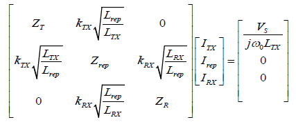 (8)
(8)
Where, represents the transformed impedance ratio of each coil (x=TX/RX/rep). From Eqn. (8), load current can be derived as;
 (9)
(9)
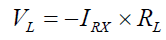
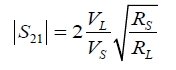
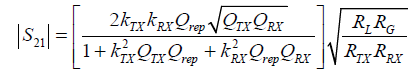
Eqn. (9) indicates that the performance of the repeater independent of the individual R-L-C values rather depends on the Q-factor of each coil (Qx=Q factor of x coil, where x=TX/RX/rep). Thus, load voltage VL can be found as, VL = −IRX × RL . In a conventional method of analysis, it is required to understand the forward wave transmission (S21) between the resonant coupled coils. Considering TX and RX coil to transmit the power for 3 coil system |S21| can be calculated [4] as followed
 (10)
(10)
PNA-X (Key-sight- N-5241A) is used to measure the practical coupling coefficient kTX and kRX for the measured distance. In a typical analysis, the |S21|can be found as
 (11)
(11)
Where, RG=RS+RPT and RRX=RL+RPR indicating the total input and output resistance of TX and RX coil respectively. The theoretical graph with respect to distances can be found by evaluating Equation 11.
To evaluate the coil transfer efficiency, it is necessary to take into account the power dissipation in TX and RX as well as the power transferred to the load. Under the given value of source and load resistances, the coupling between the TX and repeater is tuned as a function of the repeater-to-RX coupling which maximizes the efficiency. The coil transfer efficiency PTE of the WPT system can be stated computing each of the coil efficiency where;
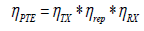
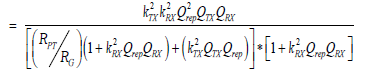 (12)
(12)
Here, and are the efficiency of TX, repeater and RX coil respectively. From Equation 12 it is clear that the coupling coefficients and Qrep plays a fundamental role for good power transmission. A theoretical analysis of PTE versus kTX and Qrep shown in Figure 3(a). From the graph, it is observed that weak coupling between the TX to repeater coil provides a better performance with a selected Qrep. Typically, the majority of power loss occurs in TX section rather than the repeater. It is because the loss in TX coil consists of coil conductor loss along with the driving circuitry losses, whereas the repeater loss contains only conductor loss. So that, overall performance greatly depends on the whereas;
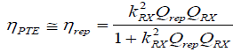 (13)
(13)

Figure 3a: S21 versus normalized coupling distances between resonators using theoretical and experimental data.
Therefore, it is necessary to minimize Equation 14 for achieving high power transmission on the load. This can be achieved by optimum tuning of the Repeater to RX coupling according to the axial orientation between the repeater and RX coils. Taking the first derivative the optimum coupling coefficient of kRX can be stated from
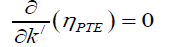 (14)
(14)
Where, 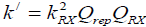 Hence, the optimum position between the repeater coils to RX coil for maximum efficiency is
found;
Hence, the optimum position between the repeater coils to RX coil for maximum efficiency is
found;
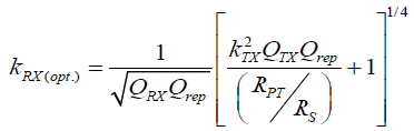 (15)
(15)
Where kRX(Opt.) is the optimum coupling coefficient at a particular optimum position between the repeater and RX coil. The power transmission and efficiency typically degrade when the position of the conventional repeater significantly deviated from the midpoint between the TX and RX coils [6]. However, the proposed flexible position tuning prevents the performance degradations and ensures adequate impedance matching without changing the original resonant frequency of the system (Figure 3(b)). The optimum tuning coupling coefficient in Equation 15 is chosen to ensure the WPT system operates with proper input and output impedances for any desired load (In this study 50 Ω). In Table 1, illustrates the experimental setup of resonant coupled WPT with a repeater coil placed at the center between the TX and RX coils. Both the TX and RX coils are designed as loop resonators (Mean diameter 14.9 cm and 0.2 cm turn spacing with 6.5 turns). Coils specifications are given below in Table 1.

Figure 3b: PTE versus normalized coil distance between resonators using theoretical and experimental data.
Table 1: Coils specification of WPT experiment.
| Coil parameters | TX coil | RX coil | Repeater coil | Remark |
|---|---|---|---|---|
| Coil radius (cm) | 7.25 | 7.25 | ~14.5 | Mean radius |
| Turn number | 2 | 2 | 6.5 | Planar Spiral |
| Pitch (cm) | 0.25 | 0.25 | 1 | AWG 18 |
| Coil inductance (µH) | 1.444 | 1.4266 | 13.185 | Measured |
| Resonant Capacitance (pF) | 734 | 742 | 80 | Measured |
| Parasitic resistance | 0.465 Ω | 0.458 Ω | 1.55 Ω | Measured |
| Q-factor | 0.887 | 0.877 | 260 | Calculated |
Load dependency using adaptive tuning is a real issue in electronics (due to a single device of capable of multi-load) (Figure 4(a)) Using a class-E PA, that is very sensitive to load changes and degrades efficiency dramatically. It is because the entire design issue will fall apart for slight changes of impedance (Figure 4(b)). Using Reflected Load Theory (RLT) to find impedance ratio transformation in WPT, a strong Impedance Matching Network holds the key operation to the primary and secondary sides for efficient coil power transfer (Figure 5(a)). In this study, an L-matching network is also used both at the primary and secondary end for impedance matching (Figure 5(b)). Moreover, whenever the coil separation took part, there was always an interruption of coupling coefficient which is then compensated. It is more likely the trade-off between the strong and weak coupling between kTX and kRX shown in Figure 6.

Figure 4a: Maximum PTE analysis under the optimum coupling condition comparing the data from L-matching circuit and frequency tuning method.

Figure 4b: R.M.S Output current (IL) at fixed and optimum coupling positioning.

Figure 5a: Measured current waveforms for WPT system with class E PA, at 10 cm distance.

Figure 5b: Measured current waveforms for WPT system with class E PA at 50 cm distance between the repeater and TX coils with the proposed method.

Figure 6: Electrical circuit model of 3 coils WPT showing the trade-off between kRX and kTX.
Due to the trade-off between kRX and kTX, a small change of load (RL) can also be handled using this method. It is because the coupling coefficient between the coils changes per distance, leads to an impedance ratio changes and thus a reflected load to the source. By considering the optimum coupling this coil transfer efficiency loss can be ignored. An adapting tuning between kTX and kRX also made difference from other works. Flat gain or flat transfer efficiency is found using the optimum coupling technique in this study. From Figure 3(b), a sharp increment of coil transfer efficiency is found up to 20 cm, and then it reaches a maximum and decreases as per the coil separation distances.
In this research, an entire WPT link is developed with the optimum tuning mechanism. Multi-coil resonators are employed to enhance the operation for higher distance. An experiment is conducted to prove the theory and its development. As we know that the coil separation will degrade the entire WPT link and hence the PTE and also the mismatch of impedance, alignment, and resonant frequency will create sub-resonance, the link development is considered under all these circumstances. In this paper, a system is brought under the optimum coupling mechanism at dynamic matching impedance whereas the resonant frequency kept fixed during the operation. The method introduced is developed and verified to enhance to PTE and distance of the multi-coil WPT link. Design guidelines considering optimum conditions are plotted using the equivalent circuit model and hence constructed during experiments. Here, the proposed method of using optimum coupling technique is served efficiently and all the empirical equations of optimum coupling values are developed by applying impedance matching principles for the optimal values of source and load resistances. The effect of coupling tuning is investigated which is conducted into two different multi-coil effects. It is simulated and verified theoretically first and proved with the experimental studies. Simulation results are in positive consent and well matched with the theoretical model. Experimental results have shown the proposed method increases the PTE up to 85% at original resonant frequency along with an extended operating range. Moreover, the proposed technique can successfully compensate the splitting of the resonant frequency and confirms adequate matching on both sides of the WPT system.