Research & Reviews: Journal of Material Sciences
ISSN:2321-6212
ISSN:2321-6212
Department of Renewable Energy Resources, Branch in Poznan, Institute of Technology and Life Sciences in Falenty, Poland
Received Date: 20/04/2017; Accepted Date: 13/05/2017; Published Date: 20/05/2017
DOI: 10.4172/2321-6212.1000166
Visit for more related articles at Research & Reviews: Journal of Material Sciences
The results of hydrodynamic of gas flow through various type of porous material kind of coal-char are presented. With respect to hydrodynamics the studies have focused on the evaluation of the permeability of such materials as a resulting from the gas flow pressure drop. It allowed determining the permeability coefficient and the pressure drop coefficient, too. Due to anisotropic structure of carbonizers the examination were performed with respect to the flow direction, i.e. directivity permeability, as a result of three-dimensional orientation for each materials sample. The results of measurements indication strongly diversified hydrodynamic parameters for investigated types of materials, and comparison of test results leads to a conclusions that the main reason of this is clear of anisotropic structure of carbonizers. In order to obtain the wider description of microstructure process conditions as the hydrodynamic result of gas flow through porous materials, attempted to use the numerical method to assessment of this process. Numerical modeling indicated the concept of gas flow through porous a tortuous structure of microchannels and micropores, together forming a porous structure with a specific geometry – both an elementary unit constituting the porous layer-bed.
Hydrodynamic, Anisotropic, Porous material, Coal-Char, Bioleaching, Biofilm, Cfd
The flow of gas by medium about the porous structure takes place in many processes areas. It is most often connected with phenomenon of filtration process as well as of migration of processes gasses in structures of porous adsorbents. With these problems we are also encountering in technological operations associated with thermal process of coals. This especially applies in the gas flow by different kinds of char-coal, the types of coke and active carbons structures. In each of these cases, recognizing conditions of flow by such structures and similar porous materials entails significant problems. They are associated with the big troubles of description of hydrodynamics, together with assessment of the mechanism of the flow of gases through porous materials with diversified configuration of inner structure. Knowledge of these mechanisms allows to evaluate the process conditions which accompany the hydrodynamics of gas flow through porous materials and, consequently, a detailed description and modelling these conditions.
The flow through porous channels with dimensions of the order of a millimetre or less, hydrodynamic phenomena are dominant over the physicochemical phenomena occurring at the interface. These latter ones are significant in flows through the structure of very small capillary size of - the order of several tenths of microns. The typical demonstration scheme of fluid flow by porous medium is presented on Figure 1.

Figure 1: Scheme of the flow of gas through porous material with sinuous microchannel (a), acc. to ref. [1], and porous space with opened and blinded channels (b), acc. to ref. [2].
Such materials are denotes by such of these quantities as porosity ε, and its flow structure depends both from the dimension (diameter) of microchannel dε and their shape - at long distance of flow Lε. In consequence, pressure drop during the around flow of sinuous walls, will differ from this one at the flow of smooth and straight channels. The literature shows that in these cases a measure of this derogation (with the adequate value) can be a calculated drag coefficient, as the resulting from the hydrodynamics flow [1,2]. With respect to the char-coal porous materials considered at the own work, the additional complexity of the hydrodynamics results also from the fact, that char-coal are the skeletal structures and so tightly clenched, and in no way cannot be loosened during a rise of pressure.
Thus, in such case the flow phenomena very substantially depend on the internal structure of porous materials, including the decomposition of the capillary channels and the forces and mechanisms forcing the gas flow – in detail described at the other own work [3].
This study assesses the selected criteria related to the hydrodynamics of gas flow through a porous material in the form of coal-char with different characteristics of its porosity. Paper presents the results of measurements with respect to permeability of such materials and the pressure drop flow units. Using numerical flow modelling methods described in the microchannels pressure change characteristic for these types of porous materials.
The experimental investigations included many different types of coal-chars. All coming by gasification processing (partial or complete) of hard coal in the real hydrodynamics assessment the quantitative evaluation of air flow through such materials was made – both for unspecified shaped samples (Figure 2a), and of uniquely defined shape in the form of a cube (Figure 2b). In both cases, an independent assessment of the physical characteristics of chars was the subject of analysis.

Figure 2: Char-coal samples: a) shapeless sample (fragment of the deposit), b) cube solid char – 20 x 20 x 20 mm.
Experimental studies in the evaluation of the permeability of the porous material were carried out under bubbling, and the carbon chars of various factories were used.
These studies were carried out on a laboratory set-up which essential element was a vessel used to assess the phenomenon of aeration through a porous samples. Experiment stand is equipped with a rotameter to measure of gas flow and pressure gauges for assessment of pressure drop. The reference pressure associated with the aeration process was determined in terms of the reducer one (0.1÷0.4) MPa. The way of supply of samples and their exemplary view is shown in Figure 3.

Figure 3: Arrangement of the air power supply (a) and the turbulent flow of gas in bubbling by shapeless sample (b).
The scope of research included determination of the apparent density and overall porosity of coal-char, estimation of permeability and – on this base – the appointment of permeability coefficient. Three different samples of char-coal were inspected. In each case there are observations of bubbling. Bubbling technique was applied with assessing of the area of the aeration by porous material.
Test results and their analysis
From the quantitative point of view the experimental research included an evaluation of such parameters as: apparent density ρo, porosity ε, permeability and equivalent coefficient of drag flow ξz. For the measurements of the permeability a volume flux of gas as a resulting from the differential pressure ΔP forcing flow was accepted. Apparent density of char-coal on the measurement of the volume of the whole body sample and for its mass was appointed out.
The measurement results characterizing the permeability of the tested char samples are presented on Figure 4a. Referred to the overall pressure drop ΔP the measured gas flow rate V flowing through the char-coal is greater when the higher is pressure of the aeration, i.e. the reference pressure of bubbling. It is compatible with the phenomenon of the flow physics. On the other side, the permeability of chars, at the given pressure value, sometimes show different characteristics, as it is taking place between samples I-1, I-2 and I-3. For comparison on Figure 4b the permeability taken back for the cubes solid char-coal is presented. Moreover, on the same figure (Figure 4b) the permeability flow for the isotropic cube solid polyamide sample (of the same dimensions) is also added. For the char the investigation results show a strongly diversified the gas flow rate relative to the flow direction. This demonstrates the high anisotropic forms of this type of materials. This phenomenon was not observed for the isotropic polyamide material, what is consistent with the physics of this phenomenon.

Figure 4: Permeability of char-coal: a) multid irectional-fractal flow (shapeless sample): ○ I-1, ● I-2, ● I-3; b) cube-solid sample: □ direction X, ■ direction Z, ■ direction Y; isotropic cube-solid sample (polyamide): ◊ direction X, ♦ direction Z, ♦ direction Y.
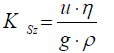
According to Szczełkaczew [4], the permeability coefficient for porous materials can be calculated such as for the laminar flow of liquid through the straight pipeline, i.e.
 (1.1)
(1.1)
Where: u - apparent velocity, m/s; η - fluid viscosity, Pa·s; g - gravitational acceleration, m/s2; ρ - density of gas, kg/m3.
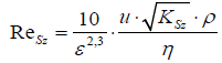
This author pointing in this way to the critical value of the number Reynolds of:
 (1.2)
(1.2)
It is worth noting, that between the laminar flow of liquid through the pipeline, and the linear flow of liquid through the porous material the partial analogies are occurring only. Among the others a linear relation between the flow rate and drag flow is presented. Regardless, the flow of gas through porous materials can be strongly dependent on the turbulent stream.
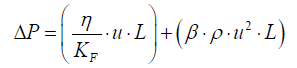
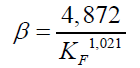
In this fact, the permeability coefficient described by Forchheimer [5,6] takes into account hydrodynamics phenomena arising from transitional and turbulent flow, as follows
 (2.1)
(2.1)
 (2.2)
(2.2)
Where: L – flow path length describing the porous bad height, m.
Parameter β in this case indicates the deviation from the linear Darcy relationship, as caused by the additional kinetics effects. Nevertheless, this parameter is not a priori and must be determined experimentally.
In the deterministic recognition, the designation of the permeability coefficient is also indicative of the method for the characteristics of the porous material, including its geometrical quantities. He depends in principle on geometrical sizes. On this basis Dullien [7], according to the theory of the hydraulic radius of Carmana-Kozeny, has made the description of permeability by introducing the effective diameter of the solid particle de and its porosity ε. According to this the permeability coefficient:
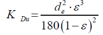 (3)
(3)
Slichter [8] also provided a description of the permeability coefficient analyzing the flow paths between particles about the same diameter and the cross section free from them (porosity bulk on this paths), namely:
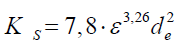 (4)
(4)
An interesting method to determine the coefficient of permeability is described by the American Society for Testing and Materials (ASTM) [9] – in this method, the description is characterized by permeability coefficient at the ambient pressure pot with the relative pressure drop ΔP to this one, according to the relastionship:
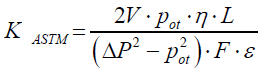 (5)
(5)
Where: V – volume flow rate, m3/s; F – cross-sectional area, m2.
It should also be noted that basing on the filtration process permeability coefficient KD of porous material, the factor value results from the pressure gradient ΔP on the filter cake layer, according to Darcy low [10], as follows:
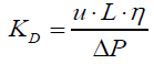 (6)
(6)
Equation (6) shows that the intensity of the fluid permeability of the porous materials affected by both the geometric parameters of the deposit, the type and properties of the fluid. There is no significance of the shape and a size of porous material. It is important that referred to the flowing of gas through a bed of granular Darcy law is valid only for the laminar flow.
The analysis of these methods indicates that the basis for evaluating of permeability coefficient is in relation of pressure drop to the permeability (volume flux) of the porous deposit. Taking into account the own investigation results and considering the possibility of laboratory evaluation tests, the equation connecting the pressure drop Pexp for a given volume flux V is described. By definition permeability coefficient KW-W is:
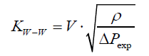 (7)
(7)
The results of calculations taking into account the conversion the permeability coefficient according to all above methods are presented on Figure 5. The distribution of experimental points has identified three areas, characteristic for the evaluated coefficient.

Figure 5: Permeability coefficient applied to the cube-char samples: ► Szczełkaczew (1), ▼ Forchheimer (2), ▲ Dullien (3), ▲ Slichter (4), ◊ Darcy (5), ♦ ASTM (6) ► own results (7).
The first indicates the dominance of the gas viscosity, which causes the permeability values decrease with the increase of the measured pressure. The permeability of the second region is constant regardless of the flow resistance. In contrast, in the third area the results show that the trend of changes in the permeability of the tested char is on the rise, with an increase in pressure. These results are also confirmed in relation to the others porous structure.
In conclusion such a trend of the change of the permeability coefficient results from anisotropic arrangement of char-coal.
For comparison, in Figure 6 results of calculations were presented according to the method of ASTM [9], put together for char-coal from chosen deposits of hard bituminous coals in the scale of world. These results are pointing for very strong tying together the structure char-coal from of them permeability of gas. Additionally it proves about distinct anisotropic of this group of materials porous.

Figure 6: Permeability coefficient applied acc. to ASTM method – the cube-char samples: ▲ (1) Czech Republic-a, ▲ (2) Czech Republic-b, ► (3) Australia-a, ► (4) Australia-b, ◊ (5) Poland-a, ♦ (6) Poland-b, ♦ (7) Poland-c, ▼ (8) USA, ▼ (9) Canada.
Considering properties of the material porous resulting from of him anisotropic, in Figure 7 given so-called values concerning calculations were described of border permeability char-coal with regard to the KW-W permeability coefficient - also in comparing to methods other authors.

Figure 7: Limiting of permeability to the cube-char (volume sample): ► (1) Dupuit i Polubarinova-Kochina [11,12], ▲ (2) Schols i Hagoort [13,14], ▼ (3) own results.
With regard to the given structure of porous material, this value is pointing at the medium permeability of the deposit at the assumption that the entire space resulting from his porosity is active for the flow of gas (at the medium porosity of the deposit). He results from the schedule of experimental points, that results of research own enough well are correlating this interdependence in procedural various aspects.
The results of experiments allowed determining the equivalent drag flow coefficient ξz. In the analogy for the local pressure drop, this coefficient was related to the measure pressure drop ΔPexp, which results from the average gas permeability and gas velocity w in the supply channel with d=6 mm of inner diameter. Thus:
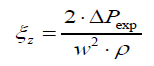 (8)
(8)
With respect to the obtained results it should point to a trend changes of this coefficient, whose values are in line with expectations, i.e. its values decreases with increasing Reynolds number Re.
In turn, the high values of ξε coefficient calculated for shapeless char result from the fact that calculations were related to the cross-section of inlet supplied channel of such sample of porous material (Figure 3). However, for the regular shape char-coal (cube sample) the measure of the permeability of the gas flow resulting from the total pressure difference, the flow inducement.
The experimental results indicate strongly differentiated hydrodynamic parameters for the study materials. Comparison of the results leads to the conclusion that the main reason for this may lie in the anisotropic structure of char-coal. This has a definite impact on the average permeability of such materials. This is confirmed by experimental results shown in Figures 4b and 8.

Figure 8: quivalent drag flow coefficient; shapeless samples: ○ I-1, ● I-2, ● I-3; cube-char samples: □ direction X, ■ direction Y, ■ direction Z.
They were making a detailed analysis of the physical structure of studied porous materials based on the scanning image of fragments of the sample karbonizatu. For this analysis randomly a field of the identification was being distinguished, using the specialist software in addition for the object image analysis (Iris - MediCom Wrocław). For the example - on Figure 9 in the field of the chosen fragment of the image marking the size of every microcanal and gaps appearing in it was shown. Applying programme graphical tools, it is possible on this base to appoint the summary surface of pores, and in the end medium porosity in the given section and average diameter of pores.

Figure 9: Scanning image of carbonate with marked field of porous material characteristics d=123 μm, ε=54.3% (mean values for the analyzed fragment).
Physical data compared in this way of porous material was used for numerical analysis. They effected proper putting together sizes measured experimentally, with regard to physical characteristics required to the computational program in addition [15]. It allowed simultaneously for selecting the computational model.
In order to obtain the better viewing and the description of microstructure hydrodynamics of gas flow through porous structures an attempt to use for the purpose of numerical calculations was made. This analysis was performed by using the finite volume method, using the Fluent ANSYS package of the Inc. The required assumption for this analysis include in particular the need to determine the geometric parameters such as shape, length and cross-section of piping and its diameter as channels flow.
Developed spatial model - Figure 10 - of examined object corresponds to the dimensions of a cube sample with edge of 20 mm and a diameter of 123 microns, computing each microchannel. For this purpose, the calculation of the number of microchannels resulting gas flow volume relative to the effective porosity of the sample was used. It was also assumed that the geometry of the mesh network corresponds to the random structure of porous material, similar to a asymmetric gas flow through micro-channels on the piping configuration of simple, curved and tortuous.

Figure 10: The geometric structure of char-coal.
Into this way, geometry of the porous space in which microchannels are isolated from themselves and constitute a interconnections system, as is the case in the real porous material. The same criteria was applied to describe the calculation of the pressure field as shown in Figure 11 – the calculation results of pressure to arrangement of microchannels is described, as characteristic for investigated porous materials.

Figure 11: Structure of gas flow - pressure area.
The developed methodology to create network geometry microchannels indicates the possibility of further proceedings calculations, according to the adequate numerical methods for the evaluation of hydrodynamics of gas flow through porous materials. This could be a major contribution to the validation of test results under real porous deposits.
Based on the literature, it was found that there is a need for research to assess the qualitative and quantitative characteristics of porous materials with anisotropic internal structure. In terms of quantitative analysis pointed to the method of determining the gas permeability in porous systems and gives an interpretation of the hydrodynamics of gas flow in porous and capillary structures. The hydrodynamics studies relate, on the one hand, to assess the conditions of the gas bubbling through the shapeless char and on the other – related to the gas flow in the elementary unit of the char. These studies made it possible to evaluate the hydrodynamic parameters such as permeability of the porous material and the resulting equivalent drag flow coefficient. In addition, the general investigation results lead to a conclusion that for char-coal materials we have very high anisotropic structure for fluid flow. In order to obtain the wider description of microstructure process conditions as the hydrodynamic result of gas flow through such materials, to use the numerical method to assessment of this process was also attempted. Obtained results confirm the correctness of the methodology of calculation and allow evaluating the hydrodynamics of gas flow through the porous materials from char-coal, in a wide range of process parameters.
The hydrodynamic results of gas flow through porous beds with skeletal structure can in many cases be used in the process calculations of hydrodynamics of gas flow through porous beds, especially in the context of biofuel of shale ore [16], biofilm formation by methanogenic microorganisms [17], Retention in the process of underground bioconversion when selecting strains of microorganisms for maximum biogas yield [18].
The work done in the framework of a project funded by the National Research and Development Centre implemented the program BIOSTRATEG, contract No. BIOSTRATEG1/269056/5/NCBR/2015 z 11.08.2015 r.