| Microstrip patch antennas are widely used in communication system due to their light weight, reliability, and low cost. Communication plays an important role in the world and almost all the communication system are changing rapidly from wired to wireless. Microstrip patch antenna can be integrated with strip line feed network and active devices. The application of microstrip antennas started in early 1970’s for missiles guidance. Varieties of array configuration of rectangular and circular microstrip resonant patches have been used extensively. Current revolution in electronic circuit miniaturization brought about by developments in large scale integration is the major contribution factor for advancement of microstrip antennas [1-8]. These antennas are very popular for microwave and mm wave applications because they offer several distinct advantages over conventional microwave antennas. Some of the advantages are small size, easy to fabricate, light weight, and conformability with the hosting surfaces of vehicles, aircraft, missiles, and direct integration with the deriving electronics. The schematic of microstrip patch antennas consists of radiating conducting patch, a conducting ground plane, a dielectric substrate sandwiched between the two, and a feed connected to the patch through the substrate as shown in Fig. 1. |
- GagandeepKaur, GeetanjaliSingla, SimranjitKaur, Design of Wideband Micro strip Patch Antenna Using Defected Ground Structur for Wireless Applications, International Journal of Advanced Research in Computer Science and Software Engineering, Volume 3, Issue 10, October 2013.
- Indrasen Singh, V.S. Tripathi, “Microstrip Patch Antenna and its Applications: a Survey” International Journals of Computer Applications in Technology, Vol. 2, No.5, pp. 1595-1599.
- Constantine A. Balanis, “Antenna theory Analysis and Design” 2nd edition, John Wiley and Sons, 2003, Vol14, pp 812.
- K. L.Wong,“Compact and Broadband Microstrip Antennas” John Wiley & Sons, 2003.
- L. H. Weng, Y. C. Guo, X. W. Shi, and X. Q. Chen. 2008, “An Overview On Defected Ground Structure”, Progress In Electromagnetics Research B, Vol. 7, pp. 173–189, 2008.
- Ashwini K. Arya, M.V. Kartikeyan ,A.Patnaik “Defected Ground Structure in the perspective of Microstrip Antennas: A Review” frequenz, Vol.64, pp. 79–84,2010.
- Ashwini K. Arya, M.V. Kartikeyan ,A.Patnaik ,“Micro strip patch antenna with Skew-F shaped DGS for dual band operation” Progress In Electromagnetics Research M, Vol. 19, pp. 147-160,2011.
- RajeshwarLalDua, Himanshu Singh, NehaGambhir, “2.45 GHz Microstrip Patch Antenna with Defected Ground Structure for Bluetooth” International Journal of Soft Computing and Engineering (IJSCE) ISSN: 2231-2307, Volume-1, Issue-6, January 2012.
- Balanis C.A. (2005) Antenna Theory: Analysis and Design, John Wiley & Sons.
- 10. Pozar D.M., and Schaubert D.H (1995) Microstrip Antennas, the Analysis and Design of Microstrip Antennas and Arrays, IEEE Press, New York, USA.
- Dr. Max Ammnan, “Design of Rectangular Microstrip Patch Antennas for the 2.4 GHz Band” Dublin Institute of Technology
- J. Huang (1983) The finite ground plane effect on the Microstrip Antenna radiation pattern, IEEE Trans. Antennas Propagate, vol. AP-31, no. 7, pp. 649-653
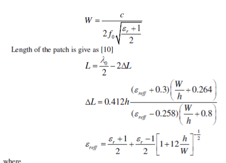
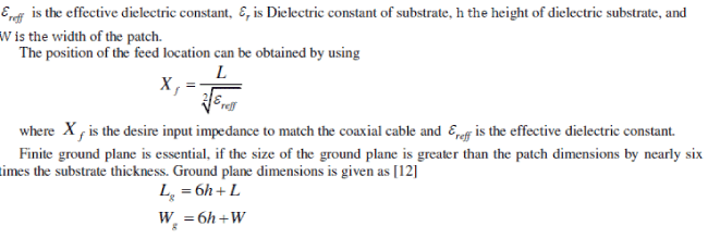
|